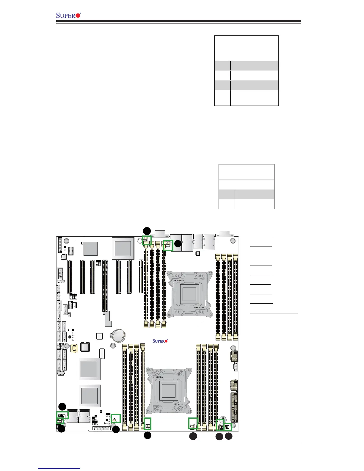
EasyManuals Logo

Supero X9DRH-7F User Manual

Supero X9DRH-7F
115 pages
To Next Page IconTo Next Page
To Previous Page IconTo Previous Page
Page #52 background imageLoading...
Page #52 background image
2-28
X9DRH-7F/-iF/-iF-NV/-7TF/-iTF Motherboard User’s Manual
JS3
SAS4-7
JPWR1
JPWR2
JTPM1
T-SGPIO1
T-SGPIO2
FANB
FANA
FAN1
FAN6
JF1
JOH1
JWD
JPB1
JPG1
JPLAN1
JBT1
BT1
J21
JD1
JIPMB1
SP1
LE1
LEDS2
DM1
VGA
JSD1
LAN1
JSTBY1
S-SATA2
S-SATA3
S-SATA1
I-SATA1
I-SATA0
S-SATA0
P2 DIMM3A
P2 DIMM3B
P2 DIMM4A
P2 DIMM4B
P1 DIMMA1
P1 DIMMA2
P1 DIMMB1
P1 DIMMB2
P1 DIMMD2
P1 DIMMD1
P1 DIMMC2
P1 DIMMC1
CPU1 SLOT1 PCI-E 3.0 x8
CPU2 SLOT4 PCI-E 3.0 x16
CPU2 SLOT6 PCI-E 3.0 x8
P2 DIMME1
P2 DIMME2
P2 DIMMF1
P2 DIMMF2
USB2/3
CPU2 SLOT7 PCI-E 3.0 x8
COM2
IPMI_LAN
FAN2
LAN2
COM1
USB0/1
P2-DIMMH2
P2-DIMMH1
P2-DIMMG2
P2-DIMMG1
Battery
JPIC21
BIOS
BMC CTRL
LAN CTRL
Intel IO Hub
LSI SAS
CTRL
SAS0-3
J22
X9DRH-7F/iF/iF-NV/7TF/iTF
Rev. 1.02
CLOSE 1st
OPEN 1st
CLOSE 1st
OPEN 1st
CPU2
CPU1
CPU1 SLOT3 PCI-E 3.0 x8
KB/MS
FAN5
CPU2 SLOT5 PCI-E 3.0 x8
CPU1 SLOT2 PCI-E 3.0 x8
JI2C1
JI2C2
I-SATA4
I-SATA5
I-SATA2
I-SATA3
JL1
FP CTRL
JPS1
LEDS1
FAN4
FAN3
USB4/5
USB6
USB8/9
T-SGPIO-S
JPME2
JPME1
A. Fan 1
B. Fan 2
C. Fan 3
D. Fan 4
E. Fan 5
F. Fan 6
G. Fan A
H. Fan B
I. Chassis Intrusion
Chassis Intrusion
A Chassis Intrusion header is located
at JL1 on the motherboard. Attach an
appropriate cable from the chassis to
inform you of a chassis intrusion when
the chassis is opened.
Chassis Intrusion
PinDenitions
Pin# Denition
1 Intrusion Input
2 Ground
C
D
F
Fan Headers
This motherboard has six system/CPU
fan headers (Fan 1~Fan 6, Fan A/Fan B)
on the motherboard. All these 4-pin fans
headers are backward compatible with
the traditional 3-pin fans. However, fan
speed control is available for 4-pin fans
only. The fan speeds are controlled by
Thermal Management via Hardware Mon-
itoring in the Advanced Setting in BIOS.
(See Chapter 5 for more details.) See the
table on the right for pin denitions.
Fan Header
PinDenitions
Pin# Denition
1 Ground
2 +12V
3 Tachometer
4 PWR (Pulse Width
Modulation)
G
A
B
I
H
E

Table of Contents

Questions and Answers:

Question and Answer IconNeed help?

Do you have a question about the Supero X9DRH-7F and is the answer not in the manual?

Supero X9DRH-7F Specifications

General IconGeneral
BrandSupero
ModelX9DRH-7F
CategoryMotherboard
LanguageEnglish

Related product manuals