FP CTRL
JPS1
LEDS1
FAN4
FAN3
USB4/5
USB6
USB8/9
T-SGPIO-S
JPME2
JPME1
B
A. JPI
2
C1
B. IPMB
A
Power SMB (I
2
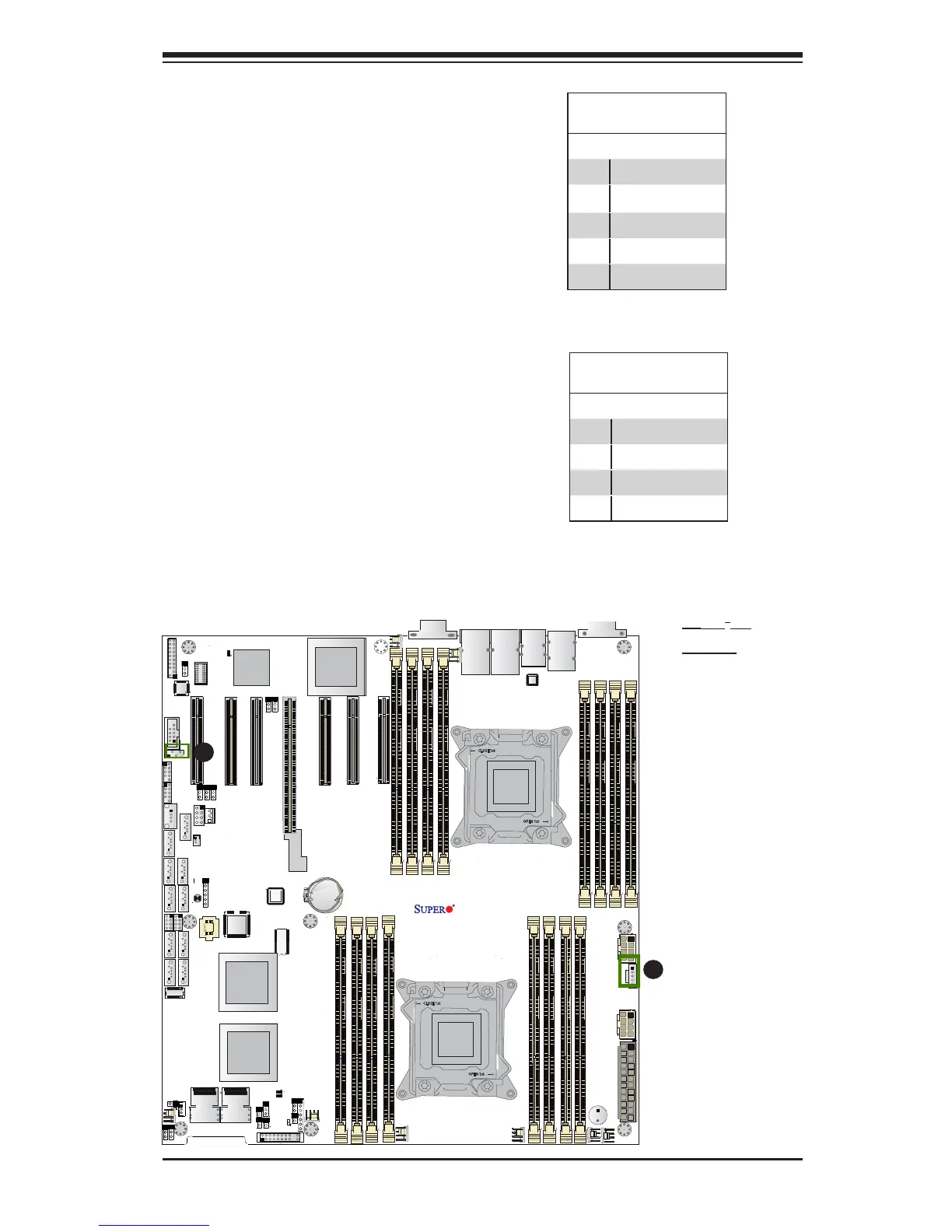
C) Connector
Power System Management Bus (I
2
C)
Connector (JPI
2
C1) monitors power
supply, fan and system temperatures.
See the table on the right for pin
denitions.
PWR SMB
PinDenitions
Pin# Denition
1 Clock
2 Data
3 PWR Fail
4 Ground
5 +3.3V
IPMB
A System Management Bus header
for IPMI 2.0 is located at JIPMB1.
Connect the appropriate cable here
to use the IPMB I
2
C connection on
your system.
IPMB Header
PinDenitions
Pin# Denition
1 Data
2 Ground
3 Clock
4 No Connection

 Loading...


