2-20
X9DRL-3F/X9DRL-iF Motherboard User’s Manual
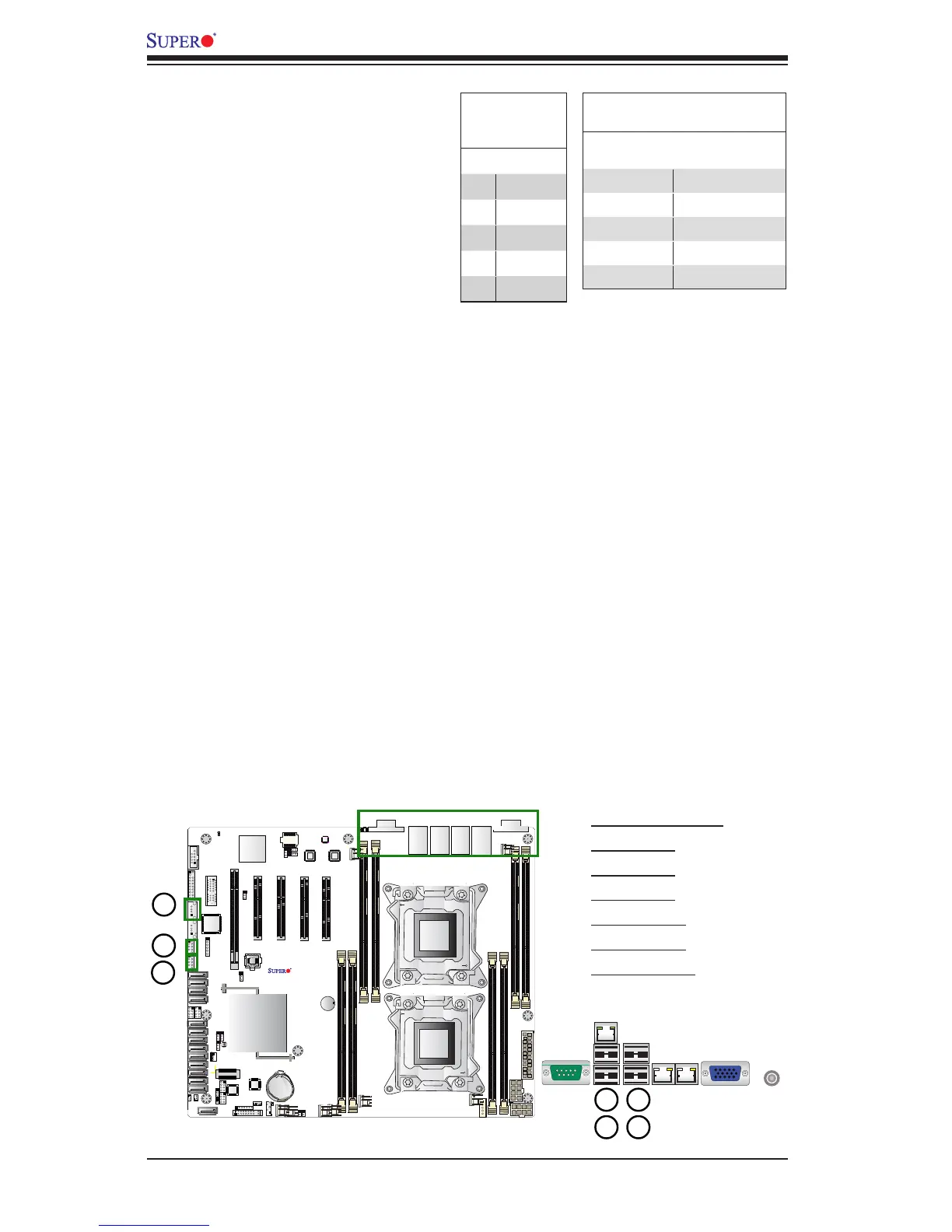
1. Backpanel USB 6
2. BP USB 7
3. BP USB 8
4. BP USB 9
5. FP USB 0/1
6. FP USB 2/3
7. Type A USB4
Universal Serial Bus (USB)
Four front accessible Universal Serial
Bus ports (USB 0/1, USB 2/3) and
two Type A USB connectors (USB4)
are located on the motherboard to
provide front USB support. In addition,
four USB ports (USB6/7, 8/9) are also
located on the backplane to provide
rear USB support. (Cables are not
included). See the tables on the right
for pin denitions.
FP USB (0/1, 2/3, USB 4)
PinDenitions
USB 0, 2, 6, 4
Pin # Denition
USB 1, 3
Pin # Denition
1 +5V 1 +5V
2 PO- 2 PO-
3 PO+ 3 PO+
4 Ground 4 Ground
5 NC 5 Key
(NC= No connection)
Backplane
USB (6/7, 8/9)
PinDenitions
Pin# Denition
1 +5V
2 PO-
3 PO+
4 Ground
5 NA
 Loading...


