2-28
X9DRL-3F/X9DRL-iF Motherboard User’s Manual
JSD1
P2-DIMMH1
P2-DIMMG1
P2-DIMMF1
P2-DIMME1
P1-DIMMD1
P1-DIMMC1
P1-DIMMB1
P1-DIMMA1
COM1
JPW4
JTPM1
LAN1LAN2
COM2
JPW1
JPW2
JPI2C1
JIPMB1
FAN3
FAN4
FAN1
FAN5
FAN2
FAN6
JPG1
JPB1
JWD1
JPME1
JWP1
JPL2
JPL1
LED2
LEDM1
JD1
JF1
6-SGPIO2
T-SGPIO1
I-SATA0
I-SATA1
SAS/SATA1
SAS/SATA2
SAS/SATA3
S-SAS4
S-SAS5
S-SAS6
S-SAS7
JL1
JI2C1
JI2C2
I-SATA2
I-SATA5
I-SATA4
I-SATA3
JBT1
JSTBY1
JRK1
UID
SLOT1 PCI-E 2.0 X1
USB0/1USB2/3
USB5
USB4
PCH
SLOT2 PCI 33MHZ
PCH SLOT3 PCI-E 2.0 X4 (IN X8)
CPU1 SLOT4 PCI-E 3.0 X8
CPU1 SLOT5 PCI-E 3.0 X8
CPU1 SLOT6 PCI-E 3.0 X8)
X9DRL-iF
Rev. 1.01
IPMI_LAN
BUZZER
KB/MOUSE
V
T
FANA
FANB
a
VGA
A
ah
USB8/9
CPU1
USB6/7
CPU2
6-SGPIO1
SAS/SATA0
Battery
JOH1
JP2
JPME2
LED1
JUIDB1
J9
JITP2
T-SGPIO2
BMC CTRL
BIOS
LAN CTRL
LAN CTRL
BMC Firmware
CPLD
Intel PCH
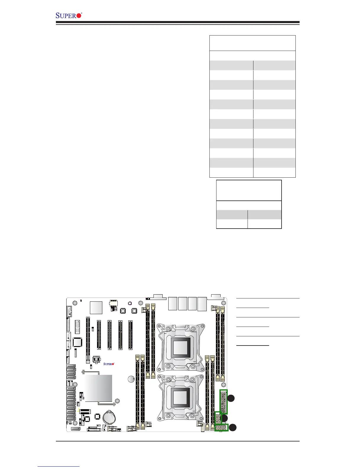
Warning: To provide adequate power supply to the
motherboard, be sure to connect the 24-pin ATX
PWR (JPW4), and the two 8-pin PWR connectors
(JPW1, JPW2) to the power supply. Failure to do so
will void the manufacturer warranty on your power
supply and motherboard.
2-7 Connecting Cables
Power Connectors
A 24-pin main power supply connector(JPW4),
and two 8-pin CPU power connectors (JPW1/2)
are located on the motherboard. These power
connectors meet the SSI EPS 12V specication
and must be connected to your power supply to
provide adequate power to the system. See the
table on the right for pin denitions.
ATX Power 24-pin Connector
PinDenitions
Pin# Denition Pin # Denition
13 +3.3V 1 +3.3V
14 -12V 2 +3.3V
15 COM 3 COM
16 PS_ON 4 +5V
17 COM 5 COM
18 COM 6 +5V
19 COM 7 COM
20 Res (NC) 8 PWR_OK
21 +5V 9 5VSB
22 +5V 10 +12V
23 +5V 11 +12V
24 COM 12 +3.3V
12V 8-pin PWR Con-
nector
PinDenitions
Pins Denition
1 through 4 Ground
5 through 8 +12V
A. JPW4: 24-pin ATX
PWR (Req'd)
B. JPW1: 8-pin Processor
PWR (Req'd)
C. JPW2: 8-pin Processor
PWR (Req'd)
A
B
C
(Required)
 Loading...


