Chapter 2: Installation
2-35
JSD1
P2-DIMMH1
P2-DIMMG1
P2-DIMMF1
P2-DIMME1
P1-DIMMD1
P1-DIMMC1
P1-DIMMB1
P1-DIMMA1
COM1
JPW4
JTPM1
LAN1LAN2
COM2
JPW1
JPW2
JPI2C1
JIPMB1
FAN3
FAN4
FAN1
FAN5
FAN2
FAN6
JPG1
JPB1
JWD1
JPME1
JWP1
JPL2
JPL1
LED2
LEDM1
JD1
JF1
6-SGPIO2
T-SGPIO1
I-SATA0
I-SATA1
SAS/SATA1
SAS/SATA2
SAS/SATA3
S-SAS4
S-SAS5
S-SAS6
S-SAS7
JL1
JI2C1
JI2C2
I-SATA2
I-SATA5
I-SATA4
I-SATA3
JBT1
JSTBY1
JRK1
UID
SLOT1 PCI-E 2.0 X1
USB0/1USB2/3
USB5
USB4
PCH
SLOT2 PCI 33MHZ
PCH SLOT3 PCI-E 2.0 X4 (IN X8)
CPU1 SLOT4 PCI-E 3.0 X8
CPU1 SLOT5 PCI-E 3.0 X8
CPU1 SLOT6 PCI-E 3.0 X8)
X9DRL-iF
Rev. 1.01
IPMI_LAN
BUZZER
KB/MOUSE
V
T
FANA
FANB
a
VGA
A
ah
USB8/9
CPU1
USB6/7
CPU2
6-SGPIO1
SAS/SATA0
Battery
JOH1
JP2
JPME2
LED1
JUIDB1
J9
JITP2
T-SGPIO2
BMC CTRL
BIOS
LAN CTRL
LAN CTRL
BMC Firmware
CPLD
Intel PCH
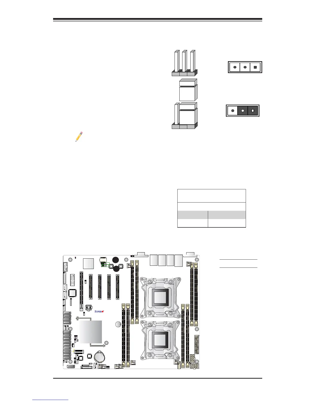
2-8 Jumper Settings
Explanation of Jumpers
To modify the operation of the mother-
board, jumpers can be used to choose
between optional settings. Jumpers create
shorts between two pins to change the
function of the connector. Pin 1 is identied
with a square solder pad on the printed
circuit board. See the motherboard layout
pages for jumper locations.
Note: On two-pin jumpers,
"Closed" means the jumper is
on and "Open" means the jumper
is off the pins.
Pin 1-2 short
3 2 1
3 2 1
GLAN Enable/Disable
JPL1/JPL2 enable or disable the GLAN
Port1/GLAN Port2 on the motherboard.
See the table on the right for jumper set-
tings. The default setting is Enabled.
GLAN Enable
Jumper Settings
Jumper Setting Denition
1-2 Enabled (default)
2-3 Disabled
A
A. GLAN1 Enable
B. GLAN2 Enable
B
 Loading...


