Chapter 2: Installation
2-11
JSD1
P2-DIMMH1
P2-DIMMG1
P2-DIMMF1
P2-DIMME1
P1-DIMMD1
P1-DIMMC1
P1-DIMMB1
P1-DIMMA1
COM1
JPW4
JTPM1
LAN1LAN2
COM2
JPW1
JPW2
JPI2C1
JIPMB1
FAN3
FAN4
FAN1
FAN5
FAN2
FAN6
JPG1
JPB1
JWD1
JPME1
JWP1
JPL2
JPL1
LED2
LEDM1
JD1
JF1
6-SGPIO2
T-SGPIO1
I-SATA0
I-SATA1
SAS/SATA1
SAS/SATA2
SAS/SATA3
S-SAS4
S-SAS5
S-SAS6
S-SAS7
JL1
JI2C1
JI2C2
I-SATA2
I-SATA5
I-SATA4
I-SATA3
JBT1
JSTBY1
JRK1
UID
SLOT1 PCI-E 2.0 X1
USB0/1USB2/3
USB5
USB4
PCH
SLOT2 PCI 33MHZ
PCH SLOT3 PCI-E 2.0 X4 (IN X8)
CPU1 SLOT4 PCI-E 3.0 X8
CPU1 SLOT5 PCI-E 3.0 X8
CPU1 SLOT6 PCI-E 3.0 X8)
X9DRL-iF
Rev. 1.01
IPMI_LAN
BUZZER
KB/MOUSE
V
T
FANA
FANB
a
VGA
A
ah
USB8/9
CPU1
USB6/7
CPU2
6-SGPIO1
SAS/SATA0
Battery
JOH1
JP2
JPME2
LED1
JUIDB1
J9
JITP2
T-SGPIO2
BMC CTRL
BIOS
LAN CTRL
LAN CTRL
BMC Firmware
CPLD
Intel PCH
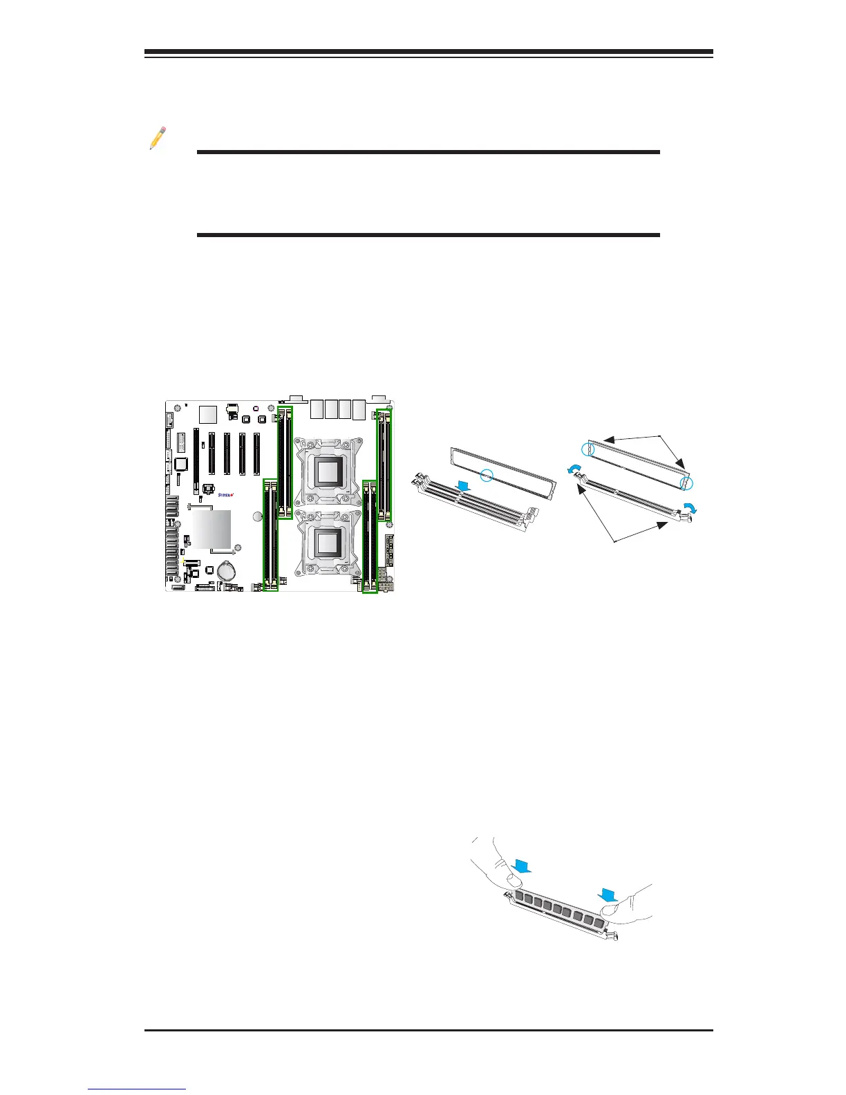
Release Tabs
Notches
2-4 Installing and Removing the Memory Modules
Note: Check Supermicro's website for recommended memory modules.
CAUTION
Exercise extreme care when installing or removing DIMM
modules to prevent any possible damage.
Installing & Removing DIMMs
1. Insert the desired number of DIMMs into the memory slots, starting with
P1-DIMMA1. (For best performance, please use the memory modules of the
same type and speed in the same bank.)
2. Push the release tabs outwards on both ends of the DIMM slot to unlock it.
Removing Memory Modules
Press both notches on the ends of the DIMM module to unlock it. Once the DIMM
module is loosened, remove it from the memory slot.
3. Align the key of the DIMM module with the receptive point on the memory
slot.
4. Align the notches on both ends of the module against the receptive points on
the ends of the slot.
5. Use two thumbs together to press the notches on both ends of the module
straight down into the slot until the module snaps into place.
6. Press the release tabs to the locking positions to secure the DIMM module
into the slot.
Press both notches straight
down into the memory slot at
the same time.
 Loading...


