EasyManua.ls Logo

suprema bioentry PLUS - Relay Connection - Fail Safe Lock; Fail Safe Lock Wiring Diagram

suprema bioentry PLUS
35 pages
Print Icon
To Next Page IconTo Next Page
To Previous Page IconTo Previous Page
Loading...
20
Copyright 2007 Suprema Inc.
Relay Connection Fail safe lock
Deadbolt /
Door strike
DC
Power supply
+ -
+
-
BioEntry Plus
(7) Normally Open / N.O. (White)
(6) Common (Blue)
(5) Normally Closed / N.C. (Orange)
N.O. (Normally Open): A control signal closes the circuit.
N.C. (Normally Closed): A control signal opens the circuit.
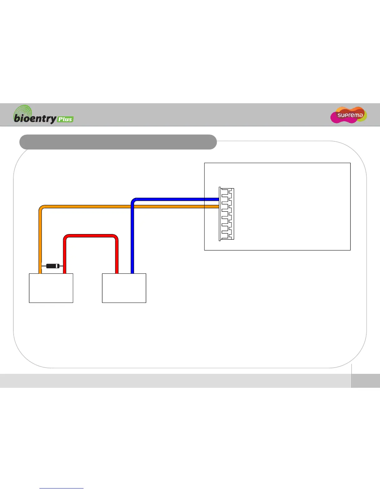
Take care of the direction of the diode.
Make sure to install the diode near to the door lock.
Make sure to use different power supplies for the BioEntry Plus and the door lock.
Make sure to install the diode at both ends of the circuit as shown in the figure above in order to protect the relay contact from the reverse current that
occurs when the door lock works.

Related product manuals