Do you have a question about the SureCall Force-5 and is the answer not in the manual?
| Maximum Gain | 72 dB |
|---|---|
| Coverage Area | Up to 5, 000 sq ft |
| Noise Figure | 5 dB |
| Impedance | 50 Ohms |
| Device Type | Cell Phone Signal Booster |
| Compatible Carriers | AT&T, Verizon, T-Mobile, Sprint, U.S. Cellular |
| Frequency Bands Supported | 700MHz, 850MHz, 1700/2100MHz, 1900MHz |
| Uplink Frequency Range (MHz) | 698-716 MHz, 1710-1755 MHz |
| Downlink Frequency Range (MHz) | 728-746 MHz, 869-894 MHz, 2110-2155 MHz, 1930-1995 MHz |
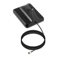
| Outdoor Antenna Type | Directional Antenna |
| Indoor Antenna Type | Panel Antenna |
| Cable Type | Low Loss RG-6 |
| Cable Length | 50 ft |
| Power Supply | AC 110-240V |
| Installation | DIY or Professional |
| Regulatory Compliance | FCC Certified |
| VSWR | < 2.0 |
| RF Connectors | N-Type |
| Power Requirements | 100-240V AC |
| Operating Temperature | -4° to +158° F (-20° to +70° C) |
Explains how the SureCall Force-5 bidirectional signal booster works.
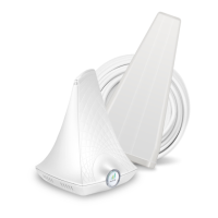
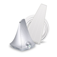
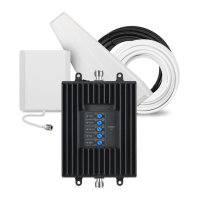
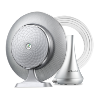
Details various antenna kits and their components for the Force-5 booster.
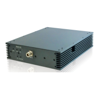
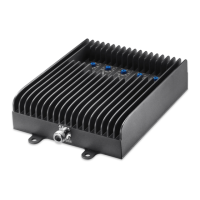
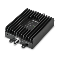
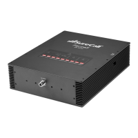
Identifies and illustrates the main hardware parts of the Force-5 booster.
Guidance on choosing an optimal location for the signal booster.
Step-by-step guide for connecting the outside and inside antennas.
Details on adjusting DIP switches to control signal amplification levels.
Explains the function of various LED indicators on the booster.
Describes the booster's automatic shutdown feature to prevent oscillation.
Provides solutions for common issues like no power or no signal.
Provides website and phone number for support and FAQs.
Details the terms and conditions of the product's two-year warranty.
Outlines limitations on warranties, damages, and liabilities.
Lists detailed technical data for the FORCE-5 signal booster.
Advises on device registration, usage, and FCC compliance.