ENGINE CONTROL SYSTEM 3-65
VSV (Vacuum switching valve)
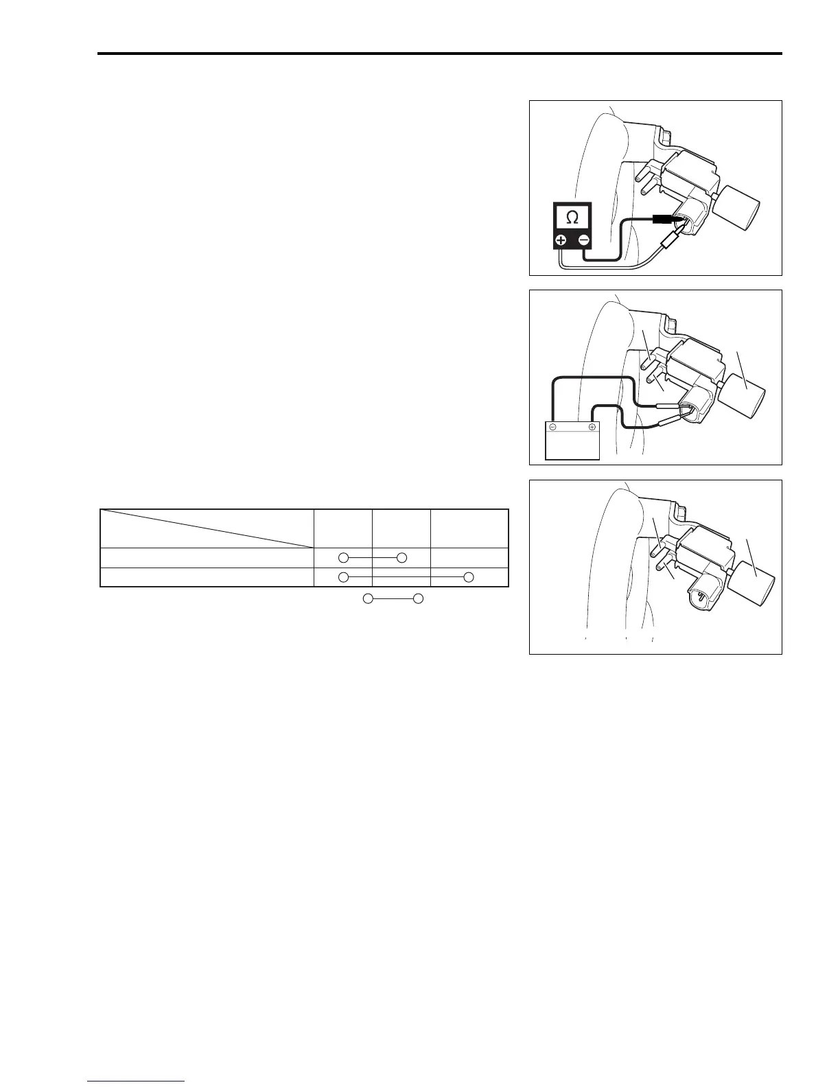
1. With ignition switch OFF, disconnect connector from VSV.
2. Check resistance between VSV terminals.
Resistance of VSV: 37 – 44 Ω
3. Disconnect two hoses from VSV.
4. With 12 V applied between the VSV terminals, check that
port (E) connects to port (F) but not to the filter section.
5. Without voltage applied to the VSV terminals, check that port
(E) connects to the filter section but not to port (F).
VSV AIR PASSAGE CONTINUITY
NOTE:
Before removing hoses to check VSV, mark each hose for posi-
tion to ensure correct hose connection on assembly.
Filter
F
E
Filter
F
E
E: To depression chamber
F: To vacuum tank
Power ON
EF
Filter
section
VSV electrical power
Passage continuity
between ports
Power OFF
: Air passage