3-18 ENGINE CONTROL SYSTEM
IGNITION CONTROL SYSTEM
OUTLINE
Sensors at specific points on the engine monitor current engine conditions and send signals to the ECM.
Based on these signals, the ECM determines the optimum ignition timing and releases voltage to the ignition
coils.
SPECIFICATION
Ignition system Full-transistorized ignition
Advance Electronic microcomputer control
Ignition timing
BTDC 0° – BTDC 26° (DF200)
BTDC 0° – BTDC 25° (DF225)
BTDC 0° – BTDC 26° (DF250)
Firing order 1 – 6 – 5 – 4 – 3 – 2
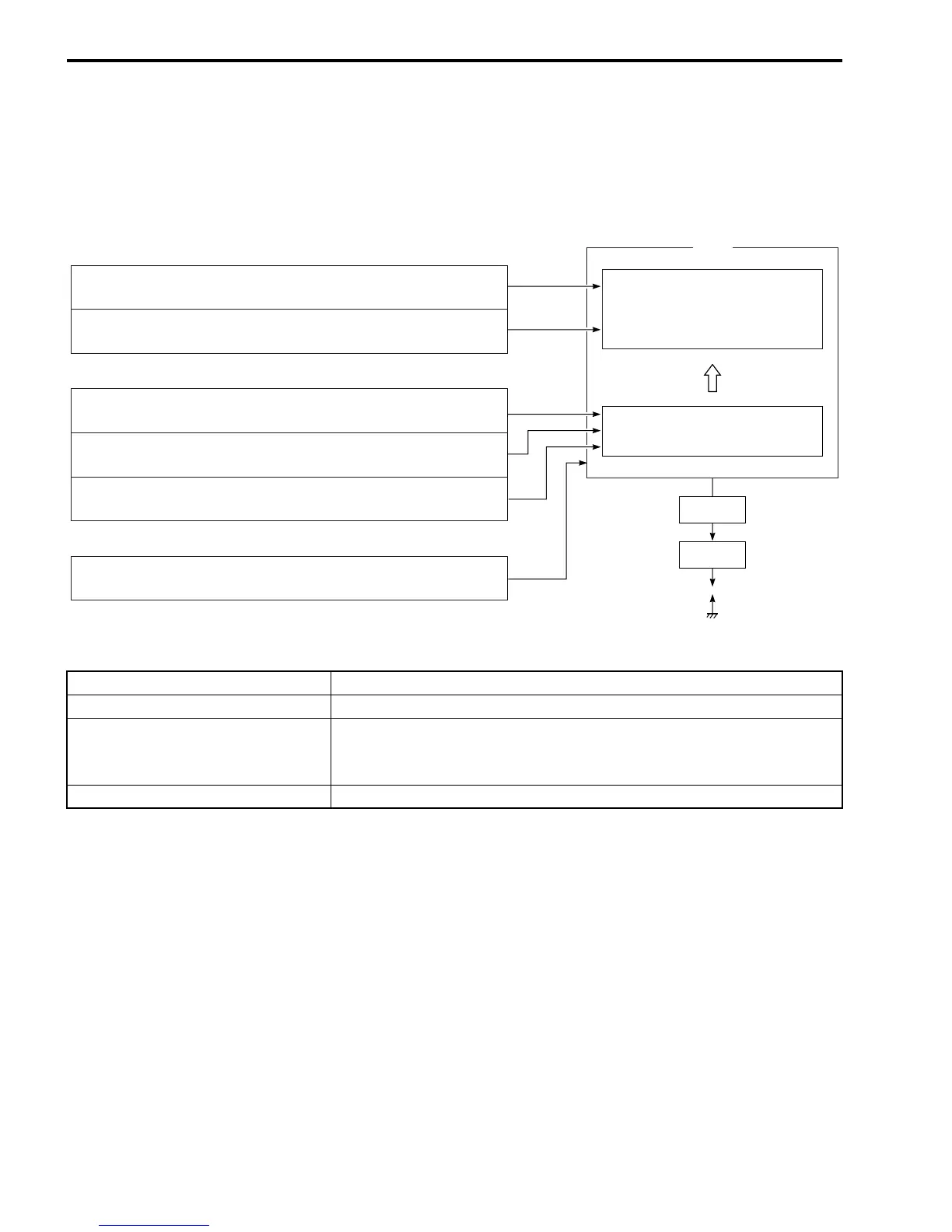
MAP sensor:
Informs ECM of collector assembly (surge tank) pressure.
CKP sensor:
Informs ECM of engine speed and crankshaft angle.
Basic sensors
Ignition switch:
Informs ECM of “START” signal.
Switch
Cylinder temperature sensor:
Informs ECM of cylinder temperature.
Throttle position sensor:
Informs ECM of throttle opening angle.
Shift position sensor:
Informs ECM of shift position and change.
Compensating sensors
ECM
Ignition timing is determined by a
digital map designed in relation to
collector assembly (surge tank)
pressure and engine speed.
Ignition timing compensation
Signal
Spark plug
Ign.coil