ENGINE CONTROL SYSTEM 3-19
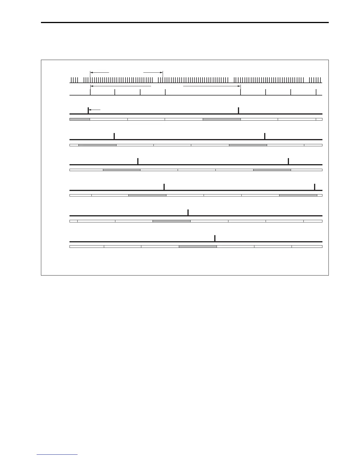
IGNITION TIMING CHART
The following chart is an example for ignition at BTDC 10°.
CONTROL MODE
WHEN CRANKING:
The ignition timing is fixed at BTDC 5° (STBD bank) or BTDC 0° (PORT bank) until the engine starts.
WHEN IDLING/TROLLING:
The ignition timing is controlled within the range of BTDC 0° ± 5° to provide stable engine operation at the
specified idling/trolling speed.
WHEN RUNNING (NORMAL OPERATION):
The ignition timing ranges between BTDC 0° – 26° (DF200), BTDC 0° – 25° (DF225) or BTDC 0° – 26°
(DF250), depending on current engine operating conditions.
In.: Intake, Cm.: Compression, Ep.: Explosion, Ex.: Exhaust
CKP
sensor
signal
CMP
sensor
#1 signal
34-signals/360˚
4-signals/720˚
Spark timing
Cm. Ep. Ex. Cm. Ep. Ex.In.
Cm. Ep. Ex.Ex. In.
Cm. Ep. Ex. Cm. Ep. Ex.In.
Cm. Ep. Ex.In.
Cm. Ep. Ex.In. Cm.In.
Cm. Ep. Ex.In. In.
Cm. Ep.In.
Ig. coil #1
Ig. coil #6
Ig. coil #5
Ig. coil #4
Ig. coil #3
Ig. coil #2
TDC TDC TDC
TDC TDC TDC
TDC TDC TDC
TDC
TDC TDC TDC
TDC TDC TDC
TDC TDC TDC
TDC