ENGINE CONTROL SYSTEM 3-11
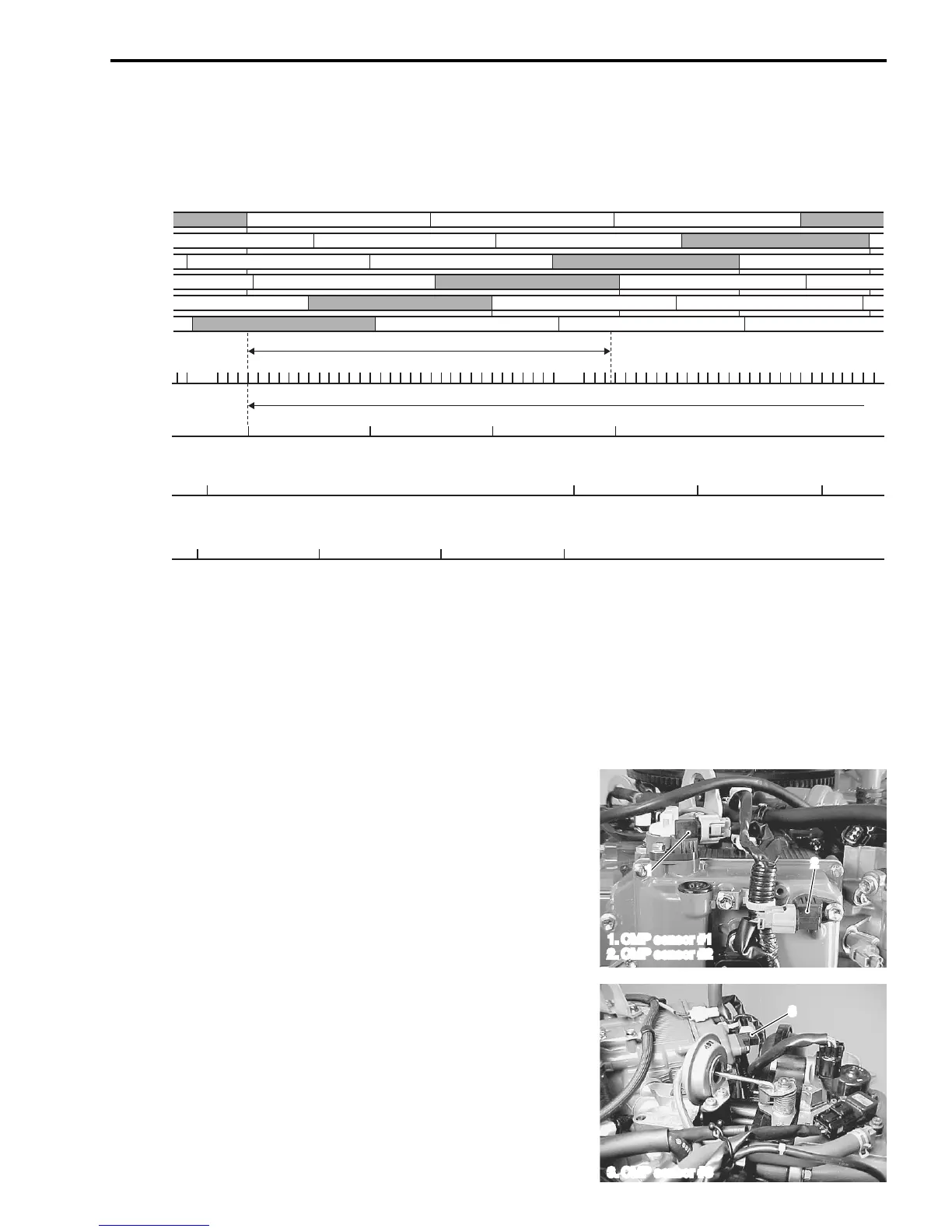
ECM cylinder identification:
Cylinders are identified by a calculation combined from two signals; one from the CKP sensor and one from
the CMP sensor.
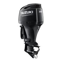
CMP (Camshaft position) SENSOR #2
• For DF250 model:
CMP sensor #2 is mounted on the PORT cylinder head cover
with trigger vanes pressed onto the end of the PORT intake
camshaft. This sensor detects camshaft position.
• This sensor is the same type as the CMP sensor #1, and
inputs signals to ECM. This signal is used to control PORT
intake camshaft valve timing through OCV (Oil control valve).
CMP (Camshaft position) SENSOR #3
• For DF250 model:
CMP sensor #3 is mounted on the STBD cylinder head cover
with trigger vanes pressed onto the end of the STBD intake
camshaft. This sensor detects camshaft position.
• This sensor is the same type as the CMP sensor #1, and
inputs signals to ECM. This signal is used to control STBD
intake camshaft valve timing through OCV (Oil control valve).
Cm.
In.: Intake, Cm.: Compression, Ep.: Explosion, Ex.: Exhaust
Ep. Ex. In. Cm.
Ep. Ex. In. Cm.
Ex. In. Cm. Ep.
Ex. In. Cm. Ep.
Cm. Ep. Ex.In.
Cm. Ep. Ex. In.
#1 Cyl.
#2 Cyl.
#3 Cyl.
#4 Cyl.
#5 Cyl.
#6 Cyl.
CKP
sensor
signal
CMP
sensor
signal #1
CMP
sensor
signal #2
CMP
sensor
signal #3
34-signals/360˚
4-signals/720˚
1
2
1. CMP sensor #1
2. CMP sensor #2
3
3. CMP sensor #3