ENGINE CONTROL SYSTEM 3-21
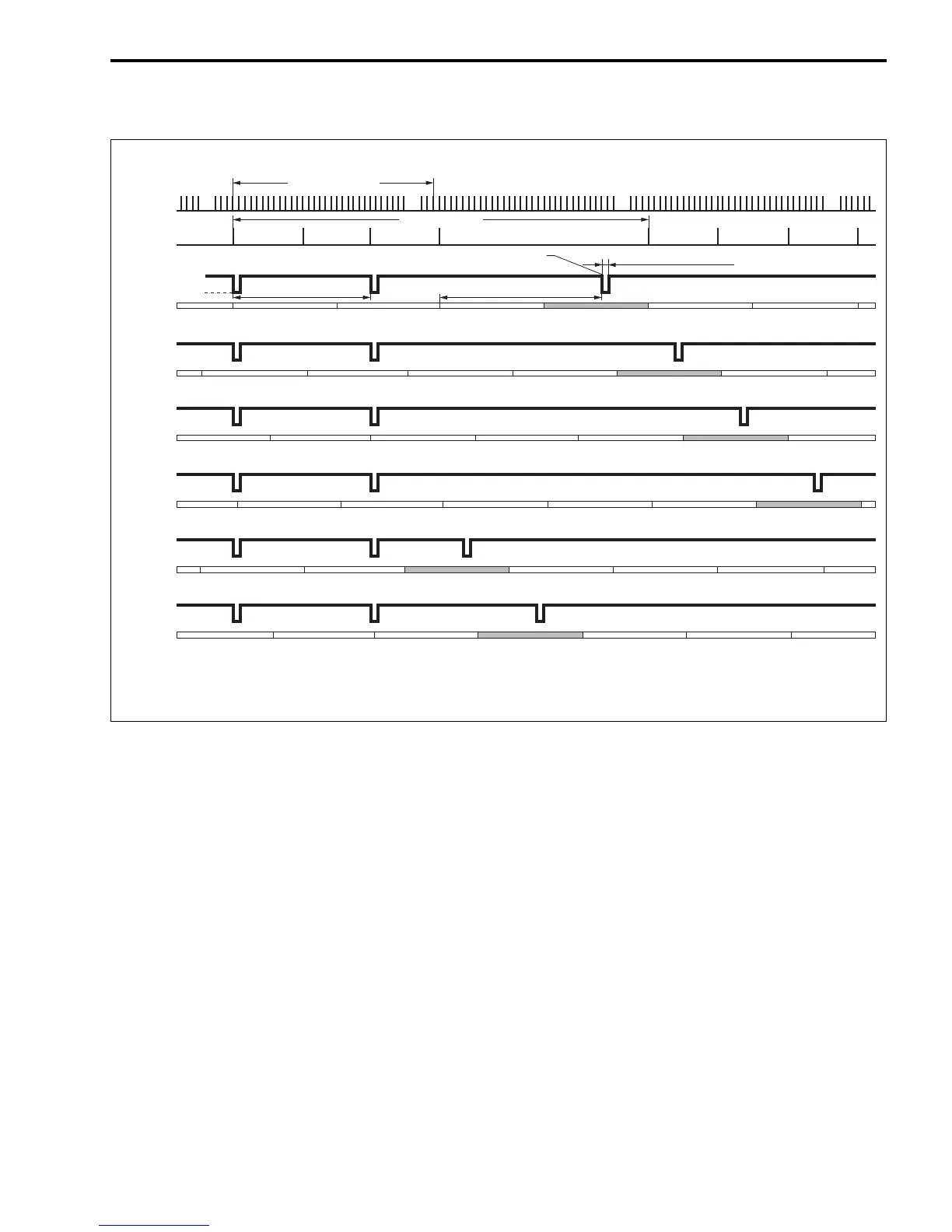
FUEL INJECTION TIMING CHART
CONTROL MODE
BEFORE START:
When the ignition switch is turned “ON”, the ECM receives a MAP sensor signal, indicating the static baro-
metric pressure of the collector assembly (surge tank). This signal is used to compensate the fuel injection
map for altitude.
WHEN CRANKING:
Fuel is simultaneously injected to all cylinders according to the “Start up mode” map in relation to crankshaft
angle.
AFTER START (FAST-IDLE FUNCTION):
The fuel injection amount is controlled to remain increased until the timer, set according to cylinder tempera-
ture at the time of engine start, expires.
WHEN IDLING/TROLLING:
The fuel injection amount is controlled to maintain a stable engine speed at the specified idle/trolling rpm.
WHEN ACCELERATING:
The fuel injection amount is controlled to increase.
WHEN DECELERATING:
The fuel injection amount is controlled to decrease.
The fuel injection is also cut off on very rapid engine deceleration.
CKP
sensor
signal
CMP
sensor
#1 signal
Ep. Ex. Cm. Ep. Ex.In.
#1
Injection
signal
#6
Injection
signal
#5
Injection
signal
#4
Injection
signal
#3
Injection
signal
#2
Injection
signal
TDC TDC TDC TDC
Ep. Ex.Cm. Cm. Ep. Ex.In.
TDC TDC TDC
Ex. Cm. Ep. Ex.In.
TDC
Cm.In.
TDC TDC
Ep. Ex. Cm.In.
TDC TDC
Ep. Ex. In.
TDC
TDC
Cm. Ep. Ep.Ex.In. Cm.In.
TDC TDC TDC
Ep.Ex. Cm.In.
TDC TDC
Ex. Cm.In.
TDC
34-signals/360˚
4-signals/720˚
ATDC 280˚ on Ex. stroke
240˚ 280˚
Injection time duration
OFF
ON
In.: Intake, Cm.: Compression, Ep.: Explosion, Ex.: Exhaust