Charging System: 1J-3
Repair Instructions
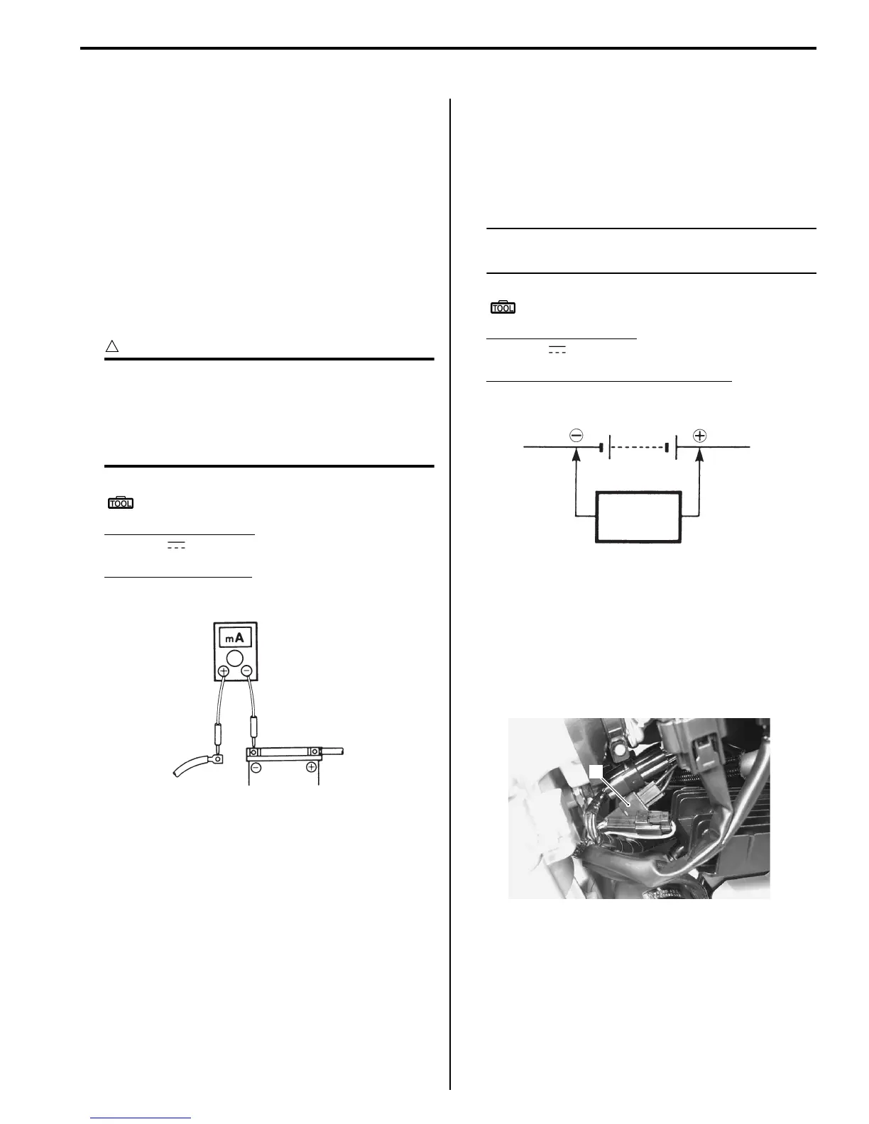
Battery Current Leakage Inspection
B817H21A06001
Inspect the battery current leakage in the following
procedures:
1) Turn the ignition switch OFF.
2) Remove the seat. Refer to “Exterior Parts Removal
and Installation (GSF650/S/A/SAK7) in Section 9D
(Page 9D-6)”.
3) Disconnect the battery (–) lead wire.
4) Measure the current between (–) battery terminal
and the (–) battery lead wire using the multi-circuit
tester. If the reading exceeds the specified value,
leakage is evident.
CAUTION
!
• In case of a large current leak, turn the
tester to high range first to avoid tester
damage.
• Do not turn the ignition switch ON when
measuring current.
Special tool
(A): 09900–25008 (Multi-circuit tester set)
Tester knob indication
Current ( , 20 mA)
Battery current (Leak)
Under 3 mA
5) Connect the (–) battery terminal and install the seat.
Refer to “Exterior Parts Removal and Installation
(GSF650/S/A/SAK7) in Section 9D (Page 9D-6)”.
Regulated Voltage Inspection
B817H21A06002
Inspect the regulated voltage in the following
procedures:
1) Remove the seat. Refer to “Exterior Parts Removal
and Installation (GSF650/S/A/SAK7) in Section 9D
(Page 9D-6)”.
2) Start the engine and keep it running at 5 000 r/min
with the dimmer switch turned HI position.
3) Measure the DC voltage between the (+) and (–)
battery terminals using the multi-circuit tester. If the
voltage is not within the specified value, inspect the
generator and regulator/rectifier. Refer to “Generator
Inspection (Page 1J-3)” and “Regulator / Rectifier
Inspection (Page 1J-8)”.
NOTE
When making this test, be sure that the
battery is in fully charged condition.
Special tool
(A): 09900–25008 (Multi-circuit tester set)
Tester knob indication
Voltage ( )
Regulated voltage (Charging output)
Standard: 14.0 – 15.5 V at 5 000 r/min
4) Install the seat. Refer to “Exterior Parts Removal and
Installation (GSF650/S/A/SAK7) in Section 9D
(Page 9D-6)”.
Generator Inspection
B817H21A06003
Generator Coil Resistance
1) Disconnect the generator coupler (1).
I649G11A0002-02
(DCV)
Tester
Battery
I649G11A0003-02
1
I717H11A0001-01