9-11
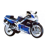
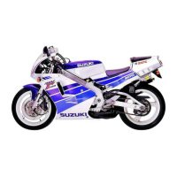
RGV250L
('90-MODEL)
ELECTRICAL SYSTEM
IGN ITION SYSTEM
Throttle sensor
Control unit
Actuator
~-t--+--------t
C.P.U.
Side
Neutral
r~nd
indicator
, sw""h
light
switch
IGNITION
C.D.1. Unit
,.
I
I
...L
I
The DC-DC converter in the CDI
unit
steps
up the battery voltage
to
a high voltage and
charges
the
capacitor (Cl. The capacitor discharges its stored energy
to
the ignition coil primary windings when the
SCR
turns on and grounds the line between the DC-DC converter and capacitor. The
SCR
turns on when
the
signal
from
the control
unit
is
sent
to
the SCR's
gate.
The moment the capacitor discharges the elec-
tricalenergy
to
the primary windings, a very high voltage
is
induced
within
the secondary windings and
a
hot
spark jumps
across
the air
gap
between the center and side electrodes
of
the spark plug.
The control
unit
determines the
SCR
gate
signal timing
to
be
best suited
for
the spark
timing
according
to
the
prevailing engine revolutions (pulser signal)
and
throttle
opening (throttle
sensor
signal).
EXHAUST
The control
unit
also
produces a signal
for
driving the actuator
to
control the exhaust valve operation. The
unit
determines the best exhaust valve
angle
for
the prevailing engine operating conditions according
to
the
signals
supplied
from
the pulser and
throttle
sensor.
 Loading...