Section II: Installation - Accessories
2.10.INS.ACC.10H92
INSTALLATION INSTRUCTIONS – TOOLBOX
1. Review all directions and
diagrams provided before
starting toolbox installation.
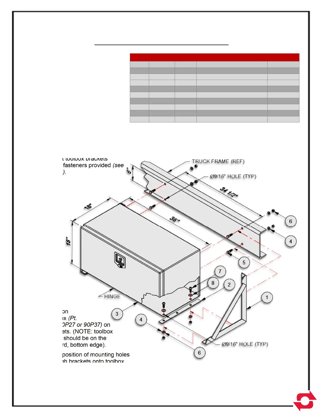
2. Position toolbox brackets
(Pt. No. 10H88) on truck
chassis (NOTE: toolbox has
an envelope of 18”x18”x36”.
see Fig. A for hole
dimensions).
3. Mark position of mounting
holes through brackets onto
truck chassis. Remove
brackets and drill 9/16” dia.
holes.
4. Mount toolbox brackets
using fasteners provided (see
Fig. A).
5. Position
toolbox (Pt.
No. 90P27 or 90P37) on
brackets. (NOTE: toolbox
hinge should be on the
forward, bottom edge).
6. Mark position of mounting holes
through brackets onto toolbox.
Remove toolbox and drill 9/16” dia. holes.
7. Mount toolbox to brackets using fasteners provided (see Fig. A).
MATERIAL LIST FOR 10H92 OR 11H12
ITEM PART # QTY DESCRIPTION WT-lb/ea.
1 10H88 2 18” Toolbox Bracket 11.34
2 22H71 2
Toolbox Rubber Spacer
.27
3 90P27 1 Aluminum Toolbox 50.00
3 90P37 1 Steel Toolbox 72.00
4 00784 8
1/2 Dia. Flat Head Washer
.07
5 00P15 4 1/2- 13 UNC x 1-3/4 .23
6 00P35 8 1/2- 13 UNC Lock Nut .15
7 00P75 4 1/2- 13 UNC x 1-1/2 .12
8 00P76 2 1/2 Dia. Nylon Flat Washer -
Note:
Will include either (1) 90P27 aluminum toolbox or (1) 90P37 steel toolbox
depending on order.
Installation is the same for both aluminum and steel toolbox.
Toolbox dimensions are 18” x 18” x 36”.
Figure A