EN
13
4.0 Description of Function
The minimal output frequency is 30 Hz (1,800 rpm)
The maximum output frequency is 4000 Hz (240,000 rpm) for ASM-motors and for DC-motors.
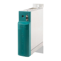
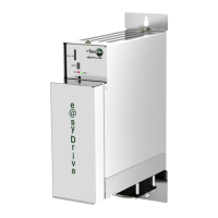
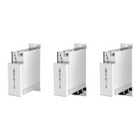
The maximum output power is 350 VA (e@syDrive 4425) and 1,000 VA (e@syDrive 4426).
The frequency inverter type e@syDrive 4425, 4426 is suitable for the variable-frequency control of various
motors, especially with high frequencies of up to 4,000 Hz corresponding 240,000 rpm. The output voltage
is set via a pulse amplitude modulation (PAM) with 120° blocks.
A 4.1 Three-phase Asynchronous Motor (ASM)
Three-phase asynchronous motors (ASM) are controlled by means of pulse amplitude modulation (PAM).
The voltage/frequency table serves as a basis for determining the motor voltage. Various control
procedures are available – controlling method IR and load compensation are provided.
4.2 Brushless DC-Motor Without Sensors (BLDC)
Brushless DC motors have a permanent magnet rotor and a fixed three-phase winding. The winding is
preferably designed as an air-gap winding with yoke, but a slotted version similar to an ASM motor is also
possible.
The motor is controlled as a function of the rotor position. The rotor position is simulated by the
frequency inverter by measuring the e.m.f. voltage from the three part-windings. No position sensors are
required. In order to permit measurement of the e.m.f. voltage, the motor inductance may not be too
large.
4.3 Brushless DC-Motor With Position Sensors (BLDCS)
The design of this motor is identical to that of the BLDC motor described above. For position detection,
however, 3 additional Hall sensors are installed in the motor.
4.4 Remote Control
The voltages at the remote control plug may be max. 60 V DC or. 25 V AC according to SELV (EN50178).
Exceptions are the relay connections, which are approved for max. 250 V AC.
All connections are potentially isolated from the control and with respect to the protective conductor.
The remote control provides a large number of programmable inputs and outputs:
6 digital inputs
PLC-compatible (24 V). The inputs IN1...IN6 are programmable with the parameters P110-input
IN1...P115-input IN6 (see chapter 4.5).
2 relay outputs
(potential-free max. 250 V~, 30 V- / 1 A) for outputting various status signals (see parameters P120-relay
REL1...P121-relay REL2).
2 analogue inputs
FB-N_soll (0...10 V) or FB-Input+, FB-Input- (0 - 20 mA) for the functions of speed setpoint default.
The programming is performed with the parameters P129-choose analog AIN
1 frequency output
(open collector, max 24 V) with one times the frequency inverter output frequency.
2 auxiliary voltages
+24 V (max. 100 mA) for wiring of the digital inputs IN1...IN6 and of the relay outputs REL1...REL2
+10 V (max. 25 mA) as auxiliary supply for external potentiometer to the analogue input AIN1