13. Electrical System
13-24
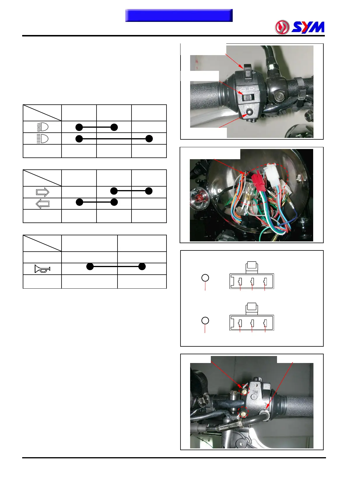
Left / right handlebar switch
Remove the headlight assembly.
Disconnect the left / right handlebar switch
wire coupler.
Check the following coupler circuit.
High / low beam switch
TL LO HI
Color Brown White Blue
Winker switch
L W R
Color Orange Gray Sky blue
Horn switch
HO E
FREE
Color Light green Green
Removal
Remove the left handlebar switch (screw x 2).
Installation
Install in the reverse order of removal.
Check if switch operation normal after
installation.
O
SB
W
BR
L
LG
Left handlebar switch
G
GR
Screw×2 Cable locknut
Dimmer switch
Winker switch
Horn switch
To this chapter contents
 Loading...