DWC ADC 12b5M SAR, TSMC180 IP Databook
April 2012 Synopsys, Inc. 14-30
7 Timing Diagrams
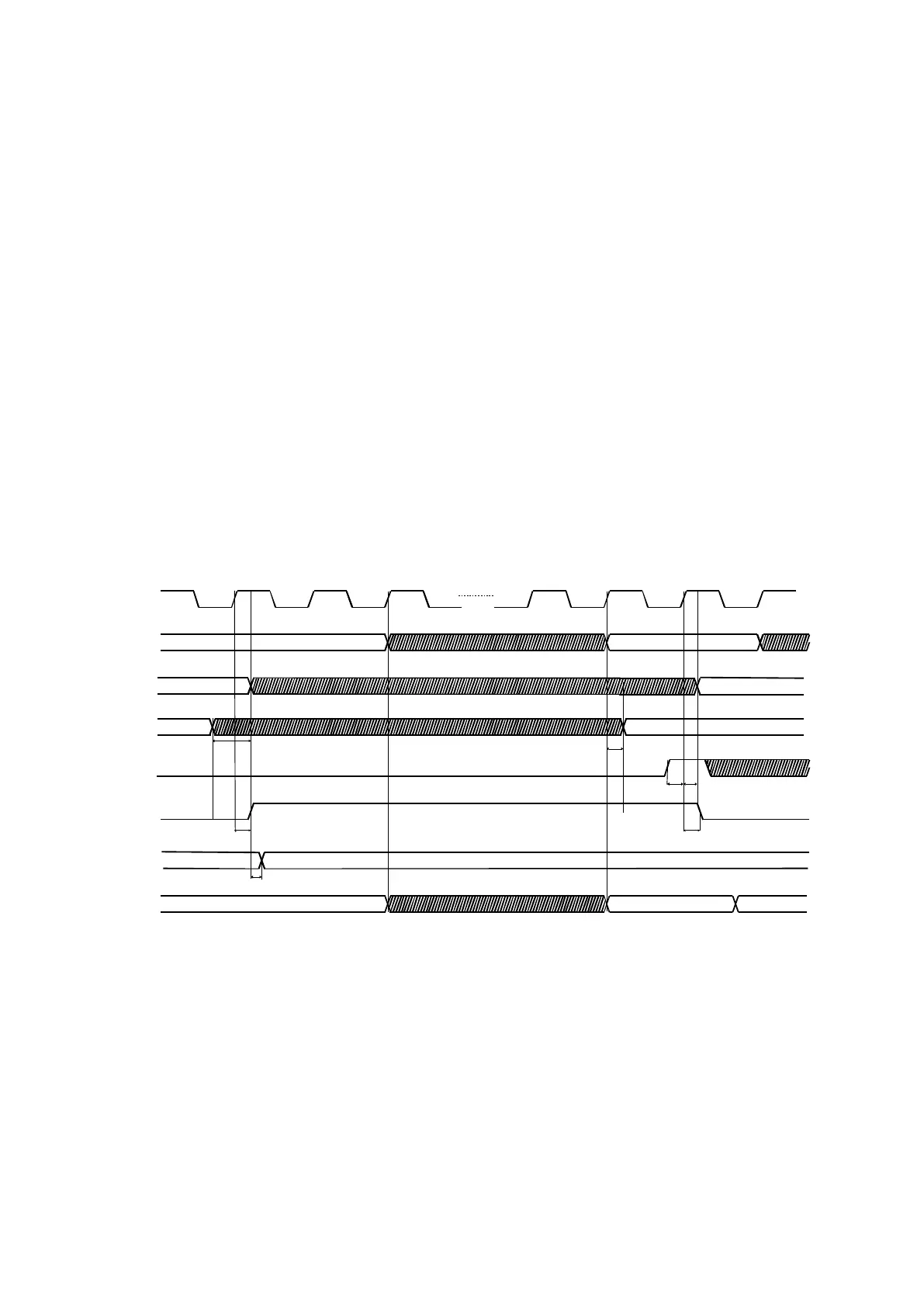
The Timing Diagram below represents the synchronization between the signals clk, soc, eoc
and the output bits. After a conversion cycle eoc is placed at high. A new conversion only
begins when soc at high level is detected. In this way, if the soc signal is held at the high
logic value, the ADC makes successive conversion cycles, achieving the maximum sampling
rate, if soc is maintained low no conversion is started.
The output data can be read fromb11...b0 (parallel outputs) or from sob (serial output). The
output code is available at b11...b0, tdata nanosecond after the rising edge of eoc. The serial
output provides each bit after it has been obtained by the internal comparator.
In case of a single conversion, where the soc signal is asserted to high only from time to
time (see diagram below).
Taking as reference the clock rising edge when soc at high level is detected:
The input selection control signals (sel0…4) must be stable during both the clock
cycle immediately before, and the one immediately after that edge.
The resolution selection control signal (selres) can only be updated after the end of
the conversion (during eoc=H).
The input mode selection control signal (seldiff) must be already stable one clock
cycle immediately before that edge.
Figure 2 – Normal operation (single conversion).
In case of successive conversions (see diagram below):
The input selection control signals (sel0…4) must remain unchanged during the last
(14
th
) clock cycle of a conversion and the first clock cycle (1
st
) of the next. This is
guaranteed by selecting the input for the next conversion, between the 2
nd
and the
13
th
clock cycles of the current conversion.
The resolution selection control signal (selres) can only be updated after the end of
the conversion (during eoc=H).
The input mode selection control signal (seldiff) can only be updated during the half
clock cycle before the end of the conversion.
tsocst tsochld
teocf
tdata
Sample Vin
N+1 N+2 1
clk
sel4..0
soc
eoc
b11... b0
Internal
S/H
Select Vin channel
Hold Vin
selres Select ADC resolution
seldiff Select ADC input mode
teocr
tclk/2
teocr