DWC ADC 12b5M SAR, TSMC180 IP Databook
April 2012 Synopsys, Inc. 10-30
6 Operating Modes
This section describes the power-up sequence and the various operating modes that the
DWC ADC 12b5M SAR, TSMC180
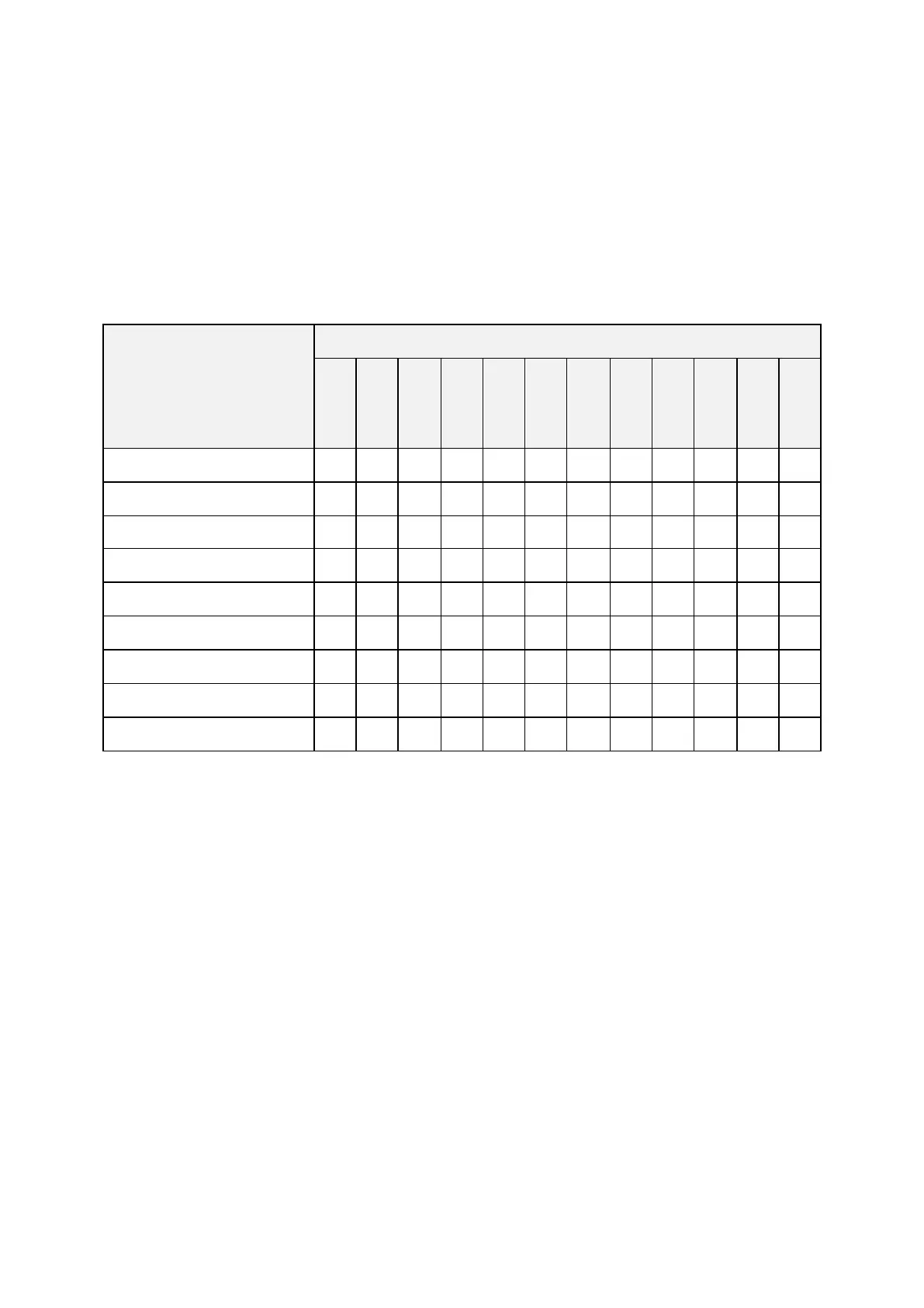
Table 2 – SAR ADC operating modes.
Normal Operation – Single-ended
Normal Operation – Differential
Calibration – Single-ended
Calibration – Differential
The following start-up sequence should be followed during system startup:
1. During the power up time of the supply voltages, ensure that enldo=L, enadc=L and
soc=L;
2. Power up both dvdd and avdd supplies;
3. Once the power supplies are stable set enldo=H and wait for the internal voltage
regulator start-up;
4. Set the resetcal signal to high during one clock cycle. There is no need to wait for the
internal voltage regulator start-up time to set resetcal to high. This signal can be set
to high right after the power supplies are stable. The only demand is to set it to high
during one clock cycle before the next step (enadc=H);
5. Set enadc=H;
6. Set the resetadc signal to high during one clock cycle;
7. For applications that require a low offset, trigger a calibration cycle using startcal, as
described in Section 8. After the calibration is complete the ADC is ready to receive
analog inputs.