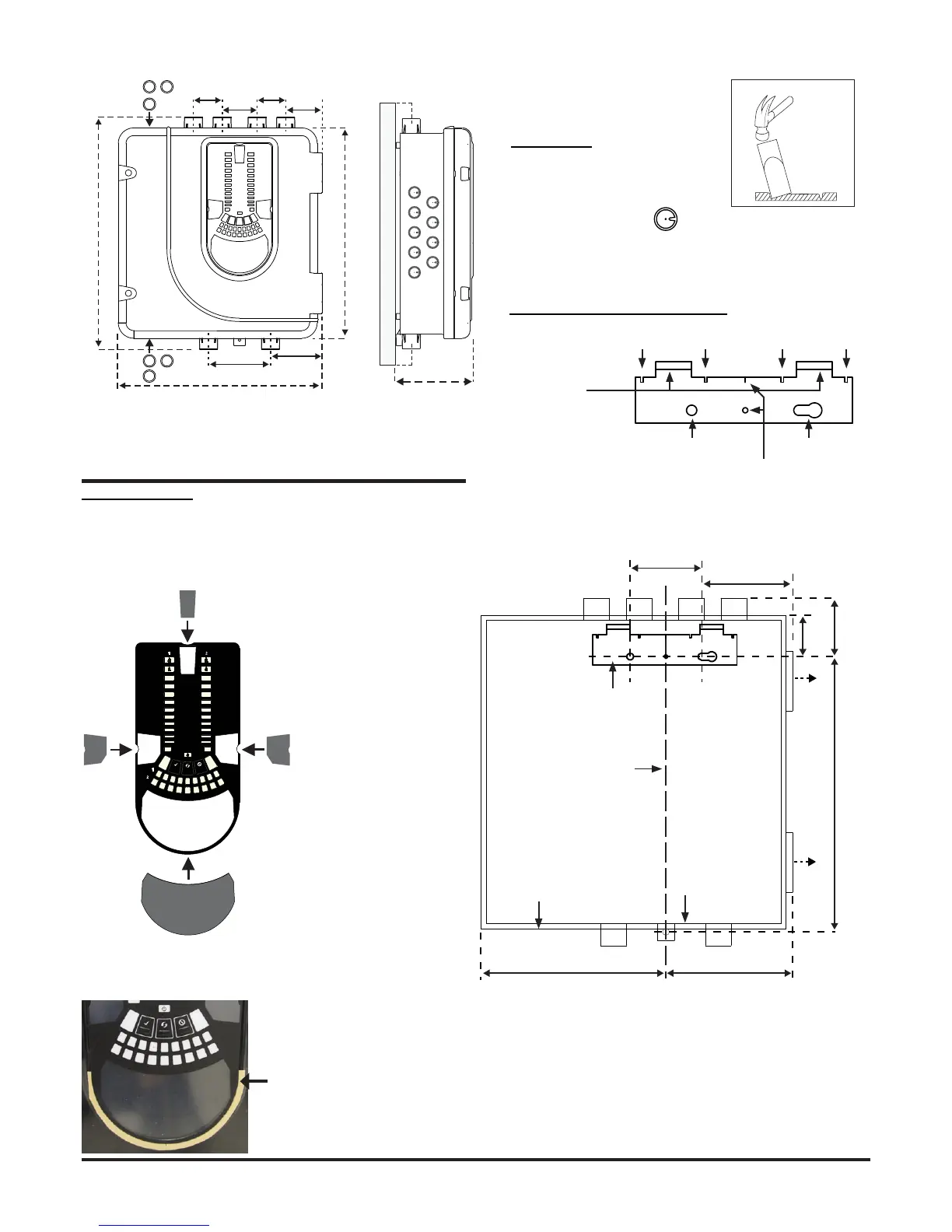
Figure 4:
How to Knock Out
Cable Gland Holes
Cable Access
Knock out cable gland holes where
required. The location of the cable
gland holes is shown in Figure 1,
represented by the icon:
Figure 2:
Placing the Front Panel Labels
Figure 6: Fasten the mounting bracket to the wall
Mounting the LT-200 FL01 to the Wall
Figure 3:
Remove Backing to
Stick Cover Down
2
10
3
1
4
5
6
7
8
9
2
10
3
1
4
5
6
7
8
9
INPUT
SENSOR
ASPIRATOR
ELBASID/MESY
TEMPERATURE
SOUNDER
FILTER
LOW FLOW
HIGH FLOW
S
T
FAULT
POWER
LEVEL 2
SMOKE
MODULE 2
MODULE 1
LEVEL 1
SMOKE
FAULT
ALARM
PREALARM
When label A is in place, remove the protector from the bottom of the
clear cover to stick the cover down, as shown in Figure 3:
Figure 5: Mounting Bracket
FAAST LT-200
HANGING LUGS
INDICATES CENTRE OF ASPIRATING PIPES
FIXING HOLE FIXING HOLE
USE FOR PLUMB-LINE
* Minimum clearance required from hinges to open door = 35 mm.
Figure 1: Dimensions and Knock-Outs
PHYSICAL INSTALLATION
Front Panel Labels
The LT-200 FL01 is shipped without the front panel labels xed in
place. This allows the installer to choose the language required for the
installation from the Front Panel Labelling Pack.
Figure 2 shows where the labels need to be placed:
A
367 mm
403 mm