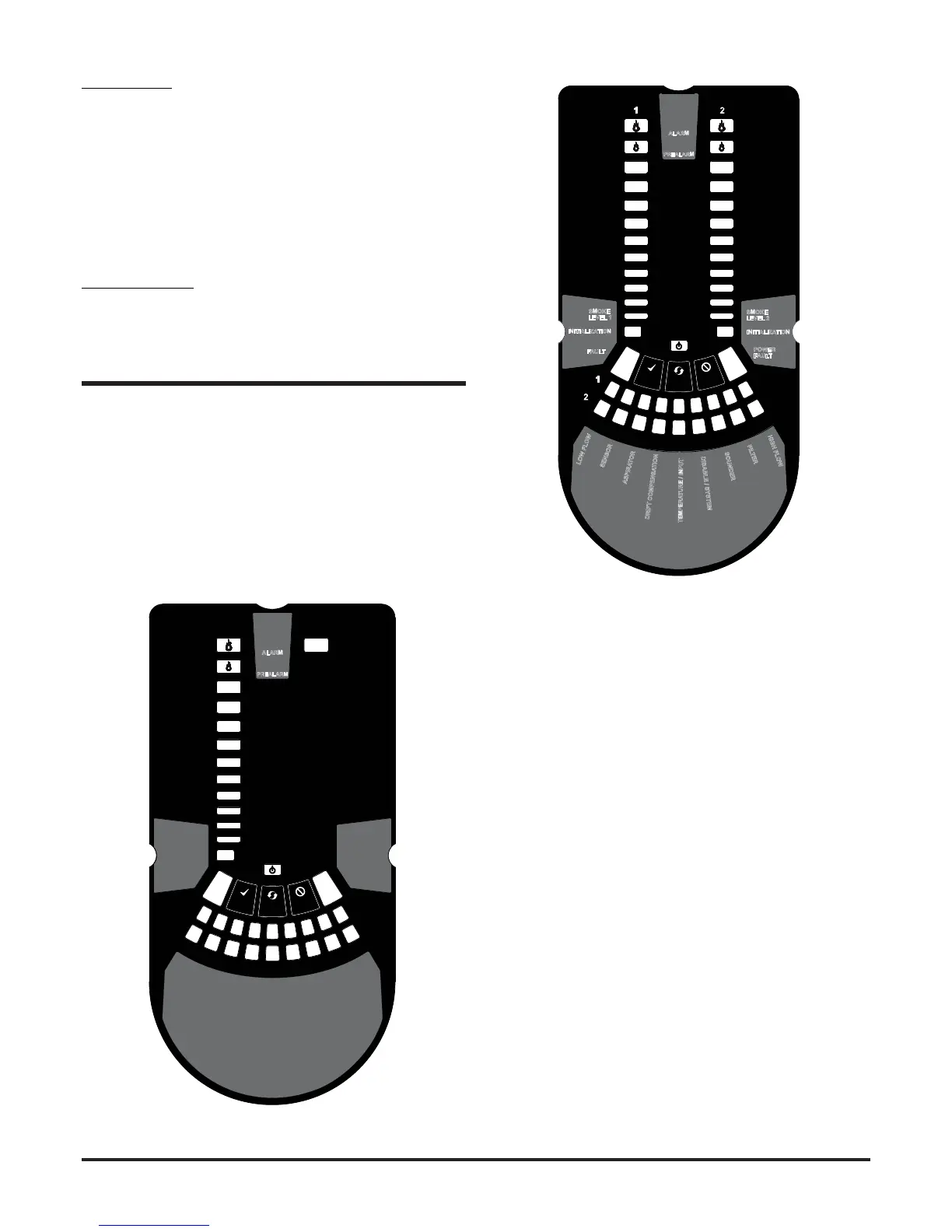
Figure 10: Front Panel Display
10a: FL0111E-HS / FL0112E-HS 1 Channel Detector
FRONT PANEL
The front panel will be dierent depending on which of the 3 FL01
models is being installed, and each is shown below.
The following information is displayed:
• Detector Status: Normal, Alarm, Fault or Isolate
• Alarm Level; Alarm, Pre-Alarm
• Particulate Levels; 1-9
• Flow Level
• Test, Reset and Disable Buttons
SE
N
S
OR
A
S
P
I
R
A
T
O
R
D
R
I
F
T
C
OM
P
E
NS
A
T
I
O
N
10b: FL0122E-HS 2 Channel Detector
POWERING UP
Using Default Settings
1. Connect a suitable 24VDC supply (complying with European
Standard EN 54-4) to pins 1 and 2 on terminal block T1 (See
Table 2)
2. Check the voltage at the connector. Make sure it is within the
required voltage range.
3. If the voltage is within the specied range, connect the power
connector to the unit.
4. Close and secure the housing door; verify the fan starts up and air
ows out of the exhaust port. The unit takes 1-3 minutes to initialise
and stabilise in normal mode.
EXTERNAL RESET
The default setting for the congurable external input is Device Reset
(terminal block T8). A momentary short circuit connection between
these terminals will cause the FAAST LT-200 unit to perform a reset.