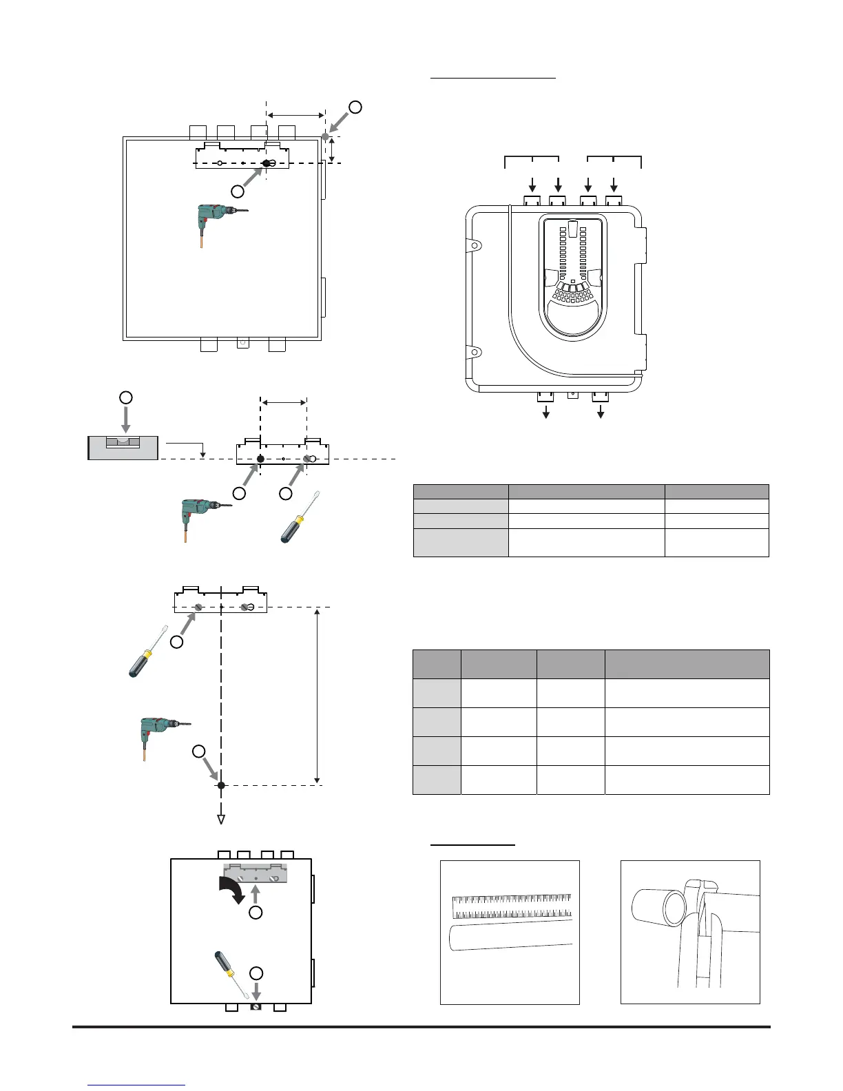
Figure 7: Sequence (1 to 9) to Mount the Detector on the Bracket
Pipe Installation
1 2 3 4 5 6 7 8 9 10 1112 13 14 1516
17 18
99 mm
41
1
2
mm
90 mm
4
3
0.00
o
5
329 mm
6
7
7a
7b
7c
7d
8
9
21
Pipe Hole Conguration
Figure 8 below shows the pipe holes available on the unit. Each unit
has 2 pipe holes per channel connected together like a T-Piece. If
using a 1 channel unit, holes 3 and 4 do not function. Use Table 1 to
locate the holes required for the installation:
Figure 8: Pipe Holes
Table 1: Pipe Holes Used for Each FAAST LT-200 Model
Note 1: Pipe holes not used should be kept sealed.
Note 2: Do NOT glue pipes into the pipe holes.
Table 1a: Maximum Number of Pipe Holes Allowed Per Channel
All gures quoted using highest (level 1) sensitivity
1
2
3
4
5
6
CHANNEL 1
CHANNEL 2 (ONLY FUNCTION
ON 2 CHANNEL UNITS)
CHANNEL 1 (NOT
USED FOR COMMON
CHAMBER UNIT)
CHANNEL 2 (ONLY
FUNCTIONS ON 2
CHANNEL AND COMMON
CHAMBER UNITS)
FAASTLTMODEL INLETPIPEHOLE OUTLETPIPEHOLE
FL0111E‐HS 1and/or2 5
FL0112E‐HS 1and/or2 6
FL0122E‐HS Channel1‐1and/or2
Channel2–3and/or4
5
6
C 100 18 6x2mm+6x2.5mm+6x3mm
(+3.5mmnonsensingendhole)
C 160(2x80)
UsingT‐Piece
18(9x2) 2x[3x2.5mm+6x3mm]
(+3mmnonsensingendhole)
B 80 6 6x4mm
(inc4mmsensingendhole)
A 80 3 1x5mm+1x6mm