Table 2: Wiring Terminal Designations
(Note - Terminals marked CH2 will only be available on 2 channel
models)
Table 3: Relays
No. Function
1 Ext Power In +
Primary PSU
T1
2 Ext Power In -
Primary PSU
3 Aux Power In +
Not used in default
4 Aux Power In -
Not used in default
5 NC Alarm Relay
CH1
T2
6 C Alarm Relay
CH1
7 NO Alarm Relay
CH1
8 NC Alarm Relay
CH2
T3
9 C Alarm Relay
CH2
10 NO Alarm Relay
CH2
11 NC Fault Relay
CH1
T4
12 C Fault Relay
CH1
13 NO Fault Relay
CH1
14 NC Fault Relay (AUX)
CH2
T5
15 C Fault Relay (AUX)
CH2
16 NO Fault Relay (AUX)
CH2
17 Sounder Output 1 -
47 k-ohm EOL Resistor T6
18 Sounder Output 1 +
19 Sounder Output 2 -
47 k-ohm EOL Resistor T7
20 Sounder Output 2 +
21 Configurable Input +
(Reset)
Default is active = short circuit
(unsupervised)
T8
22 Configurable Input -
(Reset)
23 NC Pre-Alarm Relay
CH1
T9
24 C Pre-Alarm Relay
CH1
25 NO Pre-Alarm Relay
CH1
26 NC Pre-Alarm Relay
CH2
T10
27 C Pre-Alarm Relay
CH2
28 NO Pre-Alarm Relay
CH2
Table 3a: Relay Electrical Specication
FAAST LT
R
CL
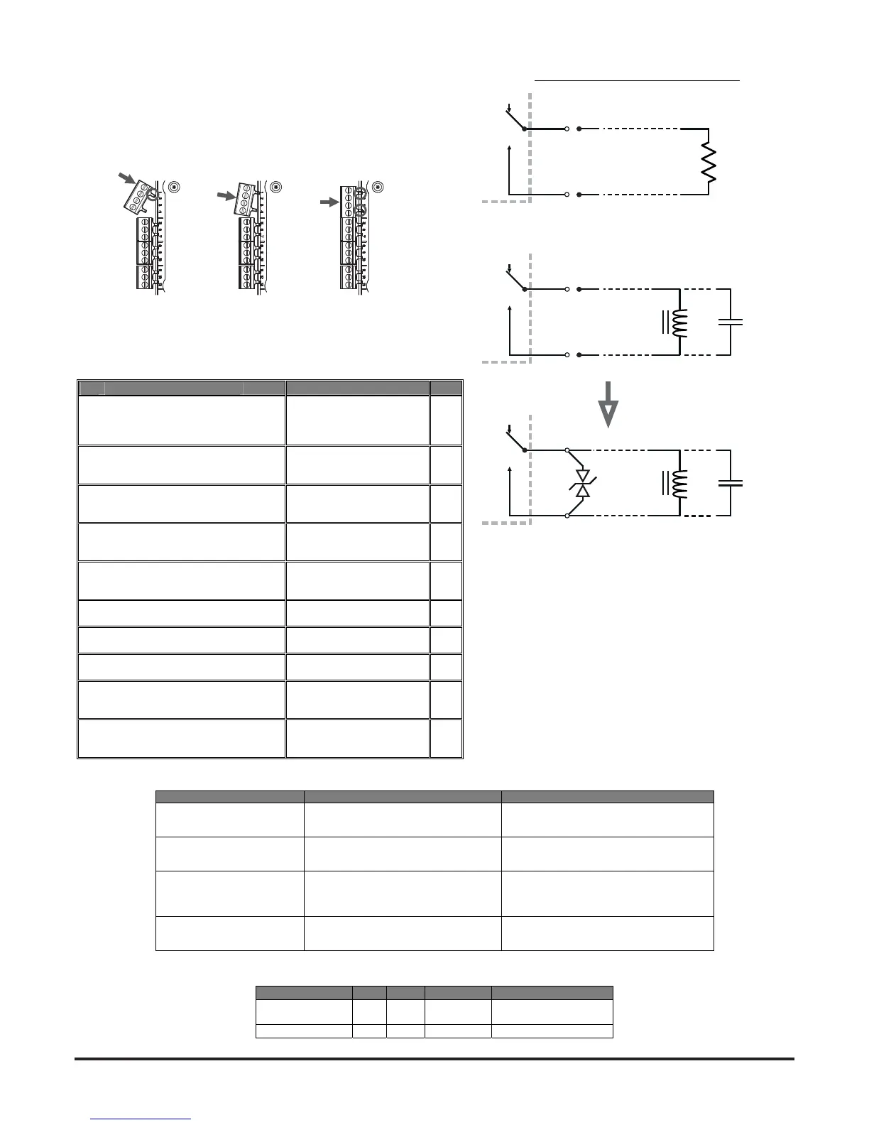
WARNING: Switching Inductive LoadsFitting the Terminal Blocks
To insert the terminal blocks into the unit use the following method:
1 Insert a corner of the block into the slot (see a).
2 Push the length of the block into the slot until the block ‘clicks’ into
place, the 2 upper hooks on the block should be visible (see c).
a b c
RELAY ACTION: NOTES
ALARM 1 or 2 Set ON when ALARM CONDITION is met
on a channel
Default condition = Level 1. Alarm state is
latched as default. A manual RESET is
necessary to deactivate LED and relay.
PRE-ALARM 1 or 2 Set ON when PRE-ALARM CONDITION
is met on channel.
Default condition = Level 1. NOTE: When
Pre-ALARM = ALARM = Level 1, Pre-ALARM
will actually respond at 70% of Level 1.
FAULT 1 or 2 When FAULT CONDITION on Ch1 or Ch2
or a common FAULT occurs. Fault is also
indicated when in SERVICE mode and
when the unit is unpowered.
Fault state is not latched (default)
SOUNDER 1 or 2 Set ON when a channel is in ALARM /
PRE-ALARM. Sounder 1 corresponds to
Ch1 and Sounder 2 corresponds to Ch2
Default condition = set on in ALARM.