Figure 11:
User Interface
Buttons
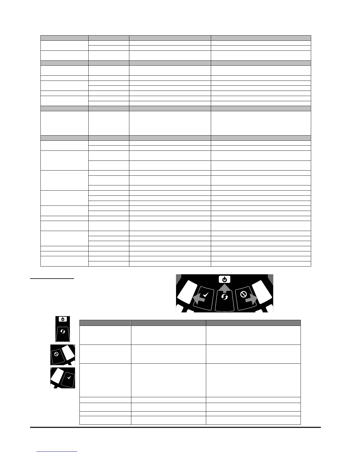
Front Panel Buttons
The front panel has 3 user buttons: TEST, RESET and DISABLE.
These buttons are used to enter the pass-code which then allows the
user to carry out simple test functions.
Note: In Remote Maintenance and Service Mode, these buttons are
always disabled.
BUTTON NORMAL Mode MAINTENANCE Mode
RESET When pressed for 2 s, starts PASSWORD
PROCEDURE to enter Maintenance
mode.
When pressed for 2 s latched alarms, faults and
sounders (relays) are reset
In DISABLE Mode, if pressed for 2 s unit will exit from
DISABLE Mode but remains in MAINTENANCE Mode
DISABLE Used to increment Password digits in
PASSWORD PROCEDURE
When pressed for 2 s, device enters DISABLE Mode
for 60 minutes (default). (Alarms, alerts and faults not
reported).
(To exit DISABLE Mode see RESET)
TEST Used to confirm password in PASSWORD
PROCEDURE. Default Password = 3111
When pressed for 2 s and released, both sensors will
simulate alarm
When pressed for 4 s and released, sensor #1 will
simulate alarm
When pressed for 6 s and released, sensor #2 will
simulate alarm
Warning: Outputs will be activated by test
COMBINATIONS
RESET + DISABLE When pressed for 2 s, shows fan speed
(on smoke level scales) for a preset time.
When pressed for 2 s, shows fan speed (on smoke
level scales) for preset time.
RESET + TEST No action When pressed for 2 s, turns off sounders
RESET + TEST + DISABLE No action When pressed for 2 s, unit exits from MAINTENANCE
Mode
Table 5: Front Panel Buttons
INDICATOR ACTION WARNING OR TROUBLE COMMENT / ACTION
CHANNEL 1/2
ALARM
ON Red Channel is in alarm (relay is set) No delay with default settings
1 BLINK Green when sensor is polled Not in alarm
CHANNEL 1/2 PRE-
ALARM
ON Yellow Channel is in pre-alarm (relay is set)
SMOKE LEVEL ON Yellow Led number indicates sensor alarm level
reached
Only numbers 1 – 9 used
INITIALIZATION ON Yellow FAAST LT is in initialization
FAULT ON Yellow Common or multiple faults
1 BLINK Yellow Fault delay Default = 60s.
POWER ON Green FAAST LT is powered
POWER FAULT ON Yellow Low / high voltage range warning Check PSU wiring and voltage.
1 BLINK Yellow Power on alert Disabled as default
CHANNEL FLOW
INDICATORS 1/2
ON Green The LED indicates the air flow for a
channel:
- Centre = normal flow
- Left = flow low; (-20% at extreme)
- Right = flow high; (+20% at extreme)
On 2 channel unit:
Upper row = Ch1
Lower row = Ch2
INDICATOR ACTION WARNING OR TROUBLE COMMENT / ACTION
LOW FLOW 1 BLINK Yellow Fault delay in progress Default is 60s; general fault set at end of delay
ON Yellow Low flow fault Check filter; check pipe network for blockages.
SENSOR 1 BLINK Yellow Sensor initialization fault Try to restart device.
Replace faulty sensor.
2 BLINKS Yellow Sensor communication fault Check sensor addresses and installation; replace
sensor.
ASPIRATOR ON Yellow Air flow sensor fault Try to restart device.
1 BLINK Yellow Flow initialization fault Check filter; check pipe network for blockages. Try
to restart the device.
2 BLINKS Yellow Fan fault Try to restart device.
DRIFT
COMPENSATION
1 BLINK Yellow Drift compensation, 1st alert Clean sensor
2 BLINKS Yellow Drift compensation, 2nd alert Clean sensor
3 BLINKS Yellow Drift compensation limit warning Sensor needs urgent maintenance
TEMPERATURE 1 BLINK Yellow Low temperature alert Check the air flow temperature
2 BLINKS Yellow High temperature alert Check the air flow temperature
INPUT 1 BLINK Yellow External input fault Not used with default settings
DISABLE 1 BLINK Yellow Alarms, faults & alerts not reported Returns to Maintenance then Normal operation
after 60min (default)
SYSTEM 1 BLINK Yellow Wrong configuration Flashes all FAULT LEDs. Try to restart device.
2 BLINKS Yellow EEPROM fault Check power supply voltage. Try to restart device
3 BLINKS Yellow Real time clock fault RTC is corrupted or time reading failed.
SOUNDER 1 BLINK Yellow Sounder fault Check the sounder circuit and the EOL
FILTER 1 BLINK Yellow Filter alert at set date No date set as default
HIGH FLOW 1 BLINK Yellow Fault delay in progress Default is 60s; general fault set at end of delay
ON Yellow High flow fault Check pipe network for breaks or leaks.