T
Y
6
8
G
3.2 Installation of the natural
balanced appliance.
For the assembling of the appliance, please follow the
instruction given in the following pages:
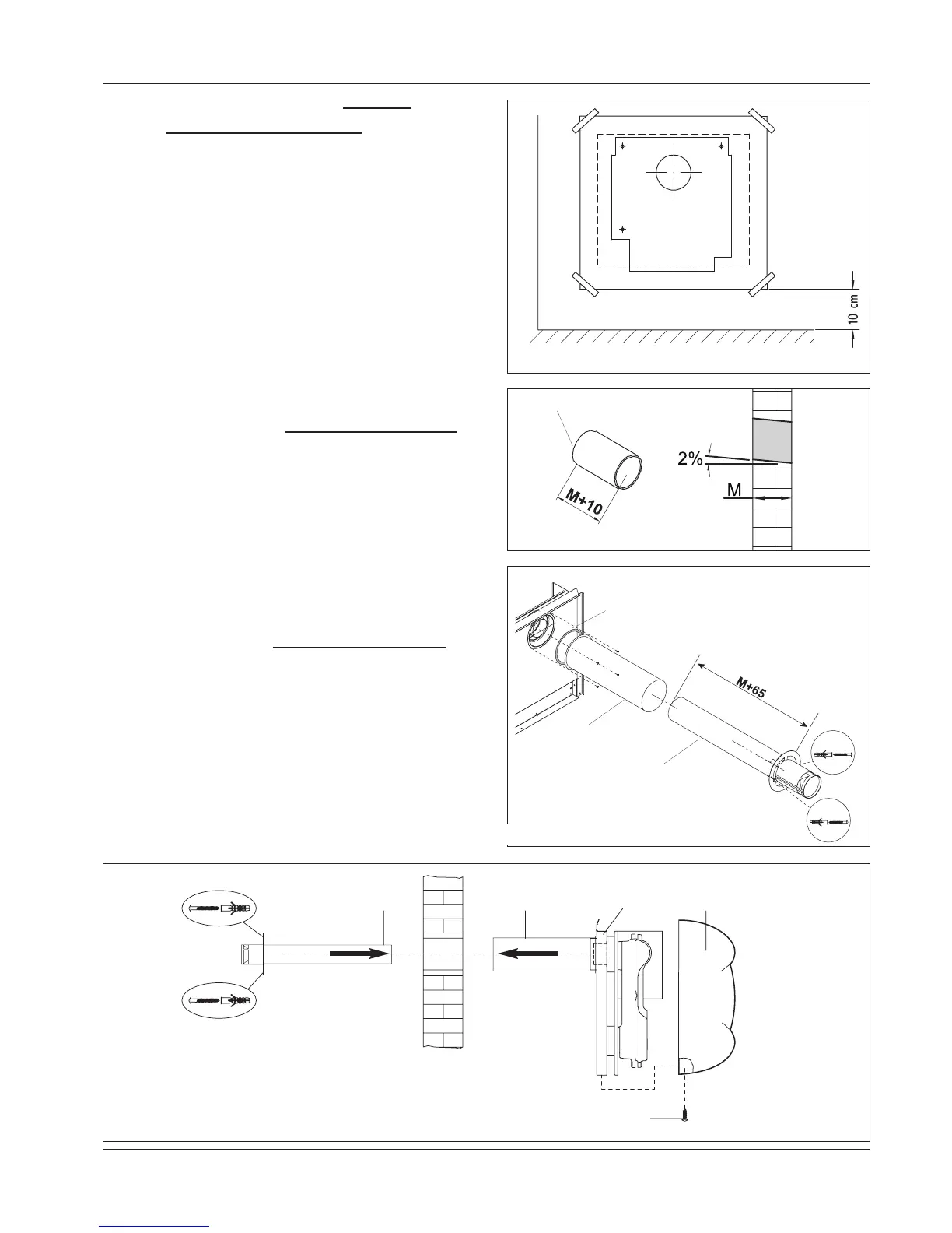
1) Place the template on the wall and fix it with adhesi-
ve tape at a distance of minimum 10 cm from the
floor perfectly in square (see draw 16). Draw the hole
for the exhaust and, if possible, make it with a 2%
inclination outwards the wall (see draw 17).
2) Place the template in square again and be careful
when centring it with the hole for the exhaust, then
make 4 holes of 8 mm in diameter and insert the sup-
plied inserts (see draw 16).
Draw 17
Draw 16
INTERNAL
GROUND
EXTERNAL
Draw 18
Draw 19
Cutting Pipes exhaust kit natural balanced models
3) When the hole is done, measure the thickness of
the wall (M).
- Cut the suction pipe (8) on the side without rim (see
draw 17) 10mm longer than the thickness of the
wall (M).
- Cut the exhaust pipe (6) 65mm longer than the
thickness of the wall (M) measuring it from the air
intake grid (G) to the end (T) of the pipe, which has
to be inserted in the convector (see draw 18).
Assembling exhaust kit natural balanced models
4) Remove the shell (1) after having unloosing the
fixing screws (2) (see draw 19)
5) Superimpose the gasket on the pipe.
- Fix the suction pipe on the side of the rim (8) with
the 4 self-threading screws supplied (see draw 22).
6) Place the convector with the supplied screws,
wedge the fumes pipe grille (6) in the internal collar
of the air box (3) and fix it on the external wall with
the two supplied inserts.