8
Draw 22
Draw 21
3.2.1 Installation of the forced applian-
ce with model grille
For the assembling of the appliance, please follow the
instruction given in the following pages:
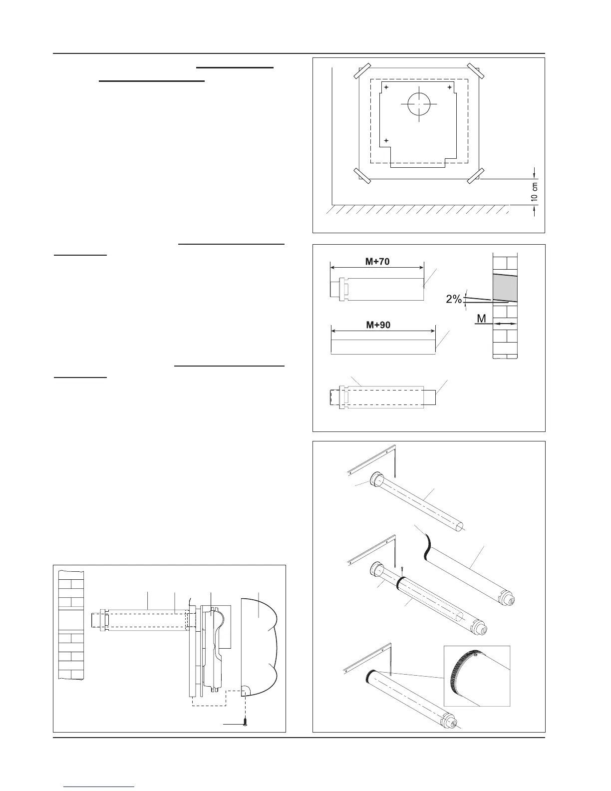
1) Place the template on the wall and fix it with adhesi-
ve tape at a distance of minimum 10 cm from the
floor perfectly in square (see draw 20). Draw the hole
for the exhaust and, if possible, make it with a 2%
inclination outwards the wall (see draw 21).
2) Place the template in square again and be careful
when centring it with the hole for the exhaust, then
make 4 holes of 8 mm in diameter and insert the sup-
plied inserts (see draw 20).
Draw 20
GROUND
Draw 23
Cutting pipes exhaust kit forced with production
model grille
3) When the hole is done, measure the thickness of
the wall (M).
- Cut the suction pipe (8) 70mm longer than the
thickness of the wall (M) and on the opposite side
of the final part (see draw 21)
- Cut the exhaust pipe (6) 90mm longer than the
thickness of the wall (M) (see draw 21).
Assembling exhaust kit forced with production
model grille
4) Remove the shell (1) after having unloosing the
fixing screws (2) (see draw 23)
5) Thread up the fumes pipe (6) in the internal collar
of the air box (see draw 22)
6) Thread up the gasket (Y) on the suction pipe (8)
(see draw 22)
- Fix the pipe (8) on the small collar (A) of the air box
using the screws supplied (see draw 22)
7) Place the convector (4) (draw 23) on the wall next
to the hole done before, and then fix it with the
screws supplied.