36
i.4.6Drainingcondensatewaterfromplateheatexchanger
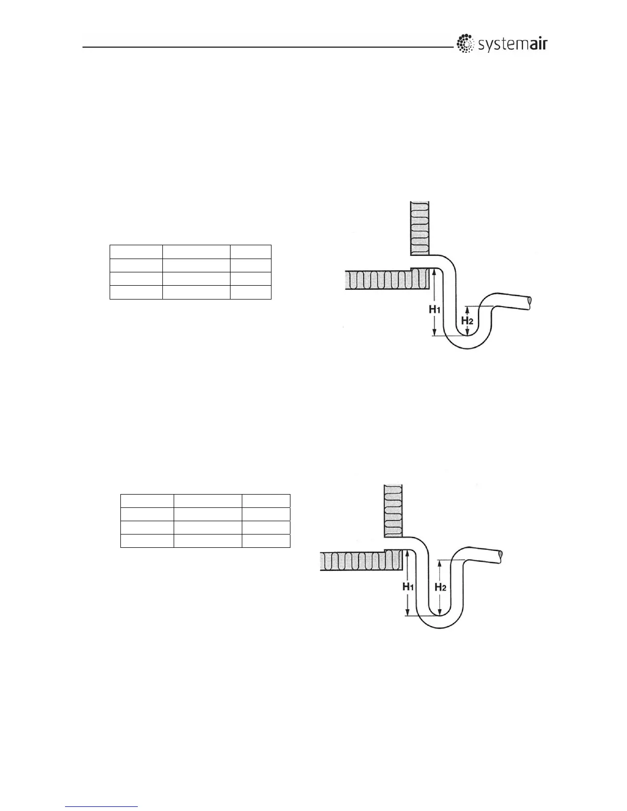
Heavynegativepressurewherethecondensatefromtheplateheatexchangeriscollectedinthedriptray
allowsairtoflowthroughthedrainagepipeintotheunitandpreventscondensatewaterfromflowingout
oftheunitthroughthedrainagepipe.Awatertrapwithsufficientclosinglevelofthe
waterisextremely
necessarytoensurethatcondensatewaterflowsoutoftheunit.Thepipediameterofthewatertrapand
sewagesystemmustbeidenticaltothepipediameterofthedrainageoutletfromthetray.
Theclosinglevelofthewatertrapmustbeestimatedcorrectlyto
ensuresafeescapeofthewater(seethe
illustrationandestimatetheminimumclosinglevelaccordingtothetable).
Awatertrapisoptionalandinstallationofthewatertrapisnotincluded.
NegativepressureP(Pa)
i.4.7Drainingcondensatewaterfromcoolingbattery
Ifthecoolingbatteryandthedriptrayareplacedintheunitwherenegativepressure(underpressure)
occurs,theclosinglevelofthewatertrapmustbeestimatedcorrectly.Seetheabove‐mentioned
informationinsectioni.4.6–Drainingcondensatewaterfromtheplateheatexchanger.
Ifthecoolingbattery
andthedriptrayareplacedintheunitwherepositivepressure(overpressure)
occurs,theclosinglevelofthewatertrapmustbeestimatedcorrectlyasshownontheillustration.Awater
trapisoptionalandinstallationofthewatertrapisnotincluded.
PositivepressureP(Pa)
P
H1Minimum H2
500Pa 90mm 65mm
750Pa 120mm 90mm
1.000Pa 150mm 120mm
j.Installationandassemblyinstructionsforreductionofnoiseand
vibrationemissions
Duetothedesignandcons tructionoftheunitsthe(A)weighedsoundpressurelevelfromfansandother
componentsdonotexceed70dB(A)outsidetheunits.
Dataaboutsoundinannex2.
P H1Minimum H2
500Pa 100mm 40mm
750Pa 150mm 55mm
1.000Pa 190mm 70mm