29
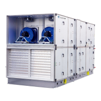
3. Sectionsaremountedtobaseframeswithlongself‐drillingscrews.Theframeprofileunderthe
inspectiondoorsisplacedoverthehorizontalprofileofthebaseframe.Seetheexampleonthe
photobelow.
i.2.7JoiningtheAHUsections
Thesectionsmustbeplacedonthebaseframeandiftheunitisdeliveredwith100mmlegs, thesections
mustbepositioneddirectlyoppositeeachother.
1.
Ensurethattheinternalfactory‐fittedrubbersealingisundamaged
2.
Thesectionsarethentobepositioneddirectlyoppositeeachother.Ifthesectionsarebuiltwith
legs,theadjustablefeetcanbeusedtogetthesectionsparallelandatthesameheight.
3.
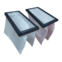
Pressthesections
hardtogethersothattherubberprofilesaresoflatthattheironframesofthe
twosectionsarejoined.Strapswithtensionerasshownbelowaresuitableforpressingthesections
hardtogether.
4.
Thesectionsarethentobelockedpermanentlytogetherwiththeblackplastic‐coatedSystemair
Disc‐Locks.TheDisc‐Locksaredeliveredinacartonboxplacedinsidetheunit.PlaceeachDisc‐Lock
overthe2factoryfittedlockingpins.Thediscsandlockingpinsarenotreliableforpullingthe
sectionstogether.Theyareonlysufficientforkeepingthesectionswelltogether,sojust
turneach
discgentlywiththesuppliedAllenkey.Useasequencewhereeachdiscistightenedwithonlyone
clickatatime.Iftheunitisplacedtooclosetoawallwithnospaceleftforthemountingof
SystemairDisc‐Locks,bracketsmustbeplacedinside
theunittokeepthesectionspermanently
together(bracketsforthispurposearenotdeliveredbySystemair)