5
CHAPTER 1 - INSTALLATION
1.1 Inspection
Inspect the inverter for any damage that may have occurred during shipping.
Check the nameplate on the iG5 inverter. Verify the inverter unit is the correct one for the application.
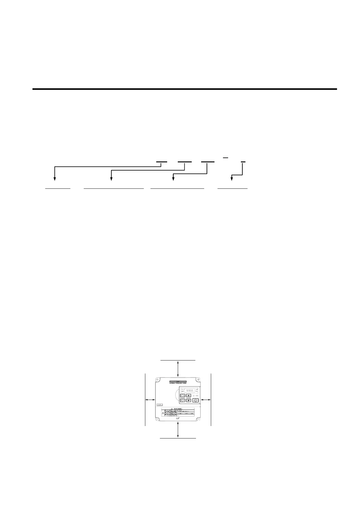
The numbering system of the inverter is as shown below.
LS Inverter Applicable motor capacity Series name of inverter Input voltage
004: 0.5 HP iG5: 0.5 ~ 5.4 HP 1: 200 ~ 230V (1 Phase)
008: 1 HP iG: 1 ~ 5 HP 2: 200 ~ 230V (3 Phase)
015: 2 HP iS5: 1 ~ 100 HP 4: 380 ~ 460V (3 Phase)
022: 3 HP iS3: 1 ~ 30 HP
037: 5.0 HP iH: 40 ~ 300 HP
040: 5.4 Hp
1.2 Environmental Conditions
Verify the ambient condition for the mounting location.
- Ambient temperature should not be below 14ºF (-10ºC) or exceed 104ºF (40ºC).
- Relative humidity should be less than 90% (non-condensing).
- Altitude should be below 3,300ft (1,000m).
Do not mount the inverter in direct sunlight and isolate it from excessive vibration.
If the inverter is going to be installed in an environment with high probability of penetration of dust, it
must be located inside watertight electrical boxes, in order to get the suitable IP degree.
1.3 Mounting
The inverter must be mounted vertically with sufficient horizontal and vertical space between
adjacent equipment (A= Over 6" (150mm), B= Over 2"(50mm)).
A
A
BB
008SV iG5 2