Do you have a question about the T-solution MASTER-K120S and is the answer not in the manual?
Explains manual usage, structure, and features of the MASTER-K120S series PLC.
Details the key features and capabilities of the MASTER-K120S series PLC.
Defines important terms used throughout the manual for clarity.
Describes the general system architecture and configuration options for the PLC.
Details the functional blocks and models of the MASTER-K120S series.
Lists the technical specifications and environmental requirements for the PLC.
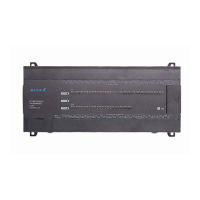
Identifies and describes the components of the PLC main unit.
Details the different types and specifications of expansion I/O modules.
Covers special modules like A/D, D/A, Analog Timer, and RTD.
Explains various communication interface modules available for the PLC.
Describes optional modules that extend PLC functionality.
Details the specifications for the PLC's power supply units.
Outlines the specifications and capabilities of the PLC's CPU.
Explains how the PLC processes operations, including scan time and modes.
Covers program classifications, execution, and interrupt handling.
Describes the different operating modes (RUN, STOP, PAUSE, DEBUG) of the CPU.
Details self-diagnosis, I/O force, and error history functions.
Explains how the PLC's memory is organized and utilized.
Describes how I/O addresses are allocated to modules.
Details the structure and usage of external memory modules.
Explains the Real-Time Clock module and its usage.
Provides general specifications for PLC input and output.
Details the specifications for digital input modules.
Outlines the specifications for digital output modules.
Covers built-in functions like High-speed counter, Pulse Catch, Input Filter, External Interrupt, PID.
Details the specifications and usage of special modules (A/D, D/A, Timer, RTD).
Explains the positioning function, parameters, and instructions.
Describes dedicated protocol communication methods and frames.
Explains how to set up and use user-defined communication protocols.
Details Modbus protocol specifications, ASCII/RTU modes, and instructions.
Covers communication without a defined protocol for flexible data exchange.
Explains remote connection methods using Cnet, modem, and Fnet I/F modules.
Provides guidelines for proper installation environment and precautions.
Details power supply wiring, I/O wiring, and grounding instructions.
Outlines general maintenance and periodic inspection procedures for PLC components.
Describes daily checks for PLC status indicators and physical connections.
Details periodic inspection steps for PLC conditions and components.
Explains fundamental steps for diagnosing and resolving system issues.
Provides flowcharts for diagnosing common LED status and operational problems.
Illustrates common circuit troubles and their corrective actions.
Lists PLC error codes, causes, and recommended corrective actions.
Covers PLC connection options and editor settings within KGLWIN software.
Explains essential PLC parameters for operation like Latch area and timers.
Lists special relays and their functions for user programming.
Details data registers used for communication and forced I/O.
Lists system error history registers when the RTC module is attached.
Details registers related to clock data.
Provides external dimensions for the PLC main units.
Shows external dimensions for standard and slim type extension modules.
| Series | MASTER-K |
|---|---|
| Type | PLC |
| Communication Ports | RS-232, RS-485 |
| Programming Language | Ladder Diagram |
| Humidity | 5% to 95% (non-condensing) |