Chapter 7 Usage of Various Functions
7-95
5) PWM output (PWM)
Available device
Flag
Instruction
M P K L F T C S D
#
D integer
No. of
steps
Error
(F110)
Zero
(F111)
Carry
(F112)
S ○
SV1
○ ○ ○ ○ ○ ○ ○
○ ○ ○
SV2
○ ○ ○ ○
○
○ ○
○ ○
○
7
○
S
Ch. for PWM output(0~1)
SV1
PWM output period( 1 ~ 20000)[ms]
Error
(F110)
Error flag turns on when designating area is over
and the instruction isn’t executed
SV2
Off Duty(0 ~ 100%)
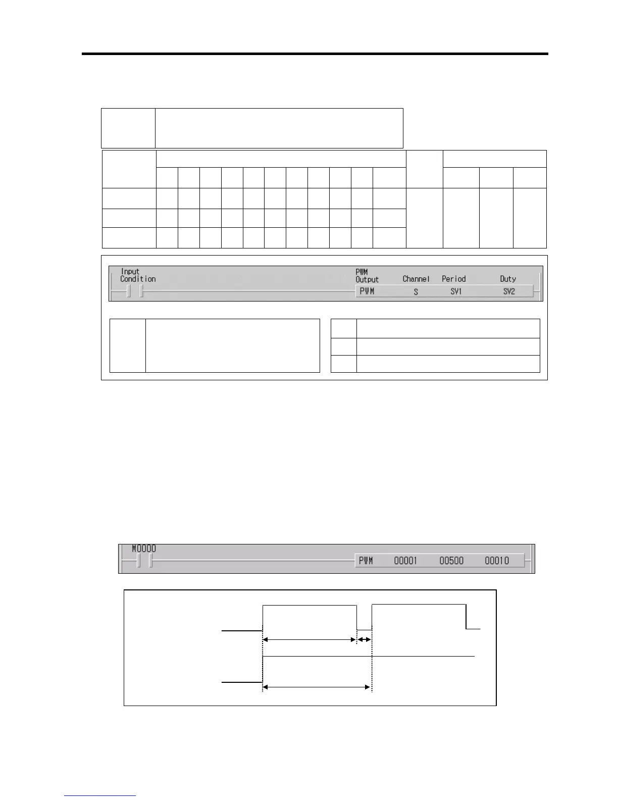
■ PWM S SV1 SV2
(1) Functions
• When input condition turns on, Output pulses which have period as SV1.
• Duty ratio of pulses is assigned by SV2.
• When input condition turns off, PWM operation stops
(2) Example program
• When input condition turns on, Output pulses as below
PWM PWM(Pulse Width Modulation) output
Desi