108
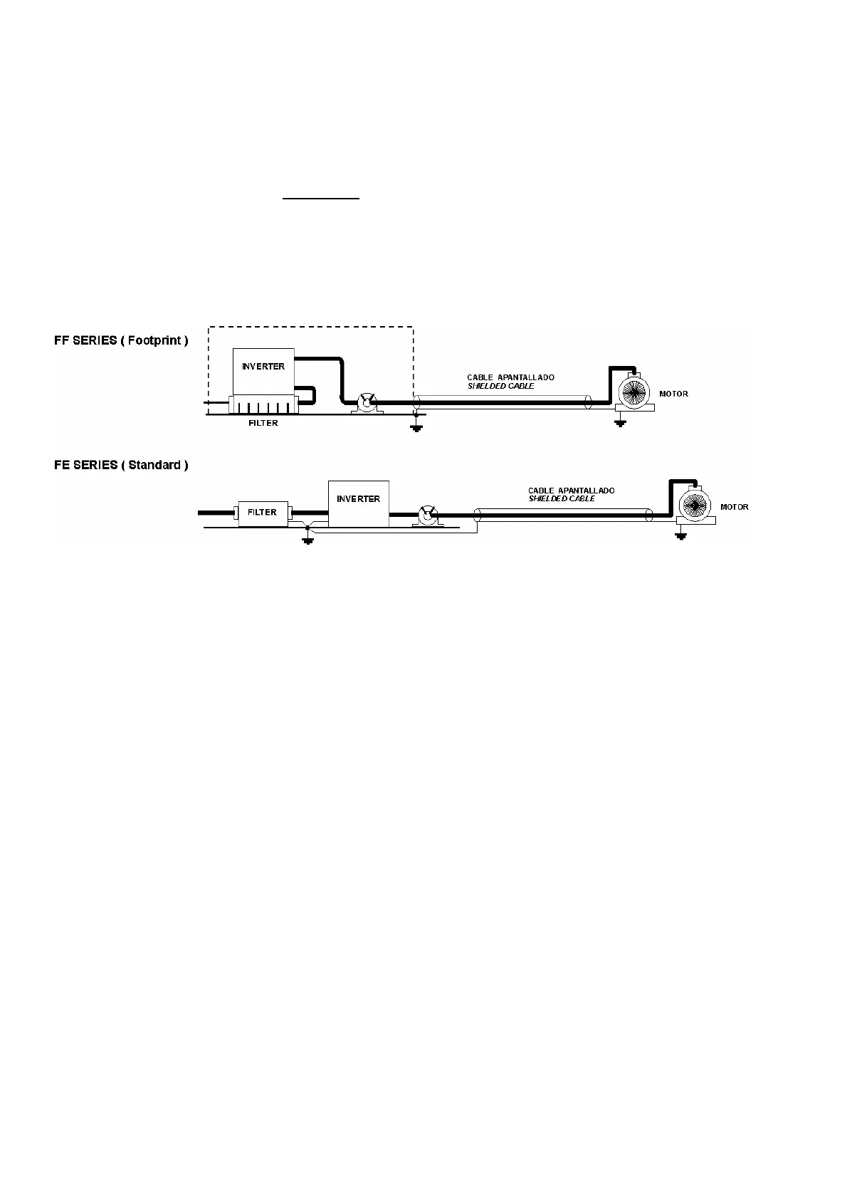
6-) Connect the motor and fit the ferrite core (output chokes) as close to the inverter as possible.
Armoured or screened cable should be used with the 3 phase conductors only threaded twice through
the center of the ferrite core. The earth conductor should be securely earthed at both inverter and motor
ends. The screen should be connected to the enclosure body via and earthed cable gland.
7-) Connect any control cables as instructed in the inverter instructions manual.
IT IS IMPORTANT THAT ALL LEAD LENGHTS ARE KEPT AS SHORT AS POSSIBLE AND THAT
INCOMING MAINS AND OUTGOING MOTOR CABLES ARE KEPT WELL SEPARATED.