14
Connecting up
CAUTION
'
Do not turn on the power switch to the
unit
or the other components until all connections have been completed.
'
When connecting components or changing connections, always set the power switch to OFF and disconnect the power
cord from its AC outlet. When making connections, connect the power cord last.
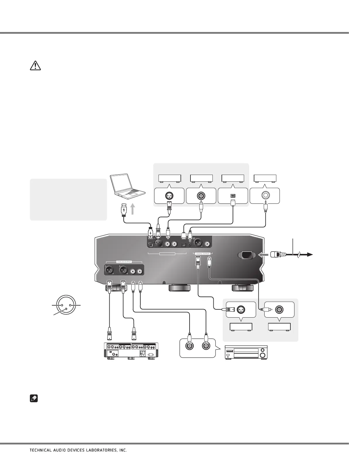
1. Connect other components.
2. Connect the supplied power cord to the unit’s AC IN connector.
3. Connect the power cord to a standard electrical outlet.
USB XLR COAXIAL OPT
DIGITAL INPUT
XLR COAXIAL
12 V
TRIGGER
OUT
D4D1 D2 D3
BALANCED UNBALANCED
L LR R
AC IN
R L
2
1
3
1. Turn on power to both the unit
and computer.
2. Switch the unit’s input to U1.
3. Using a USB cable, connect
the computer and unit; when
this is done the proper driver
will be automatically installed
(page 17).
Computer with USB port
Component with digital output connector
1: Ground
2: Hot
3: Cold
BALANCED
output connector
(XLR-3-31 equivalent)
Pre-Amplifier with balanced input connectors Pre-Amplifier with unbalanced input connectors
Power cord
(supplied)
To AC
Power outlet
Component with digital
input connector
When connecting a device equipped with the
pre-amplification feature
Note
About the balance/unbalance line output level
'
The initial value for the line output is set at 30. For details, refer to To fix the line output levels at their maximum on page 16.
In case of a power amplifier with a 12 V
trigger input terminal.
Commercially available 3.5
Φ
monaural
pin cable (without resistance)