Multitone Paging Interface Fitting Instruction 9
© Tait Electronics Limited July 2008
4. Remove the cables originally connected to the receiver module, and
User interface and put them to one side.
5. Retain the receiver DC power cable and place in the bag used above.
6. Use a Torx T10 screwdriver to remove the two screws
1).
Use a PZ1 Pozidriv screwdriver to remove the screw
j on the
heatsink of U406.
7. Carefully lift the front of the SI board off the spring clips
1!.
8. Carefully slide the SI board towards the front of the base station until
the connectors
b, c and d clear the rear panel. Lift the SI board
clear of the chassis.
Modify 1. Remove Item J104 d (240-00010-45,SKT 9wy drng 90° PCB mtg)
and put aside.
2. For XBBS104 SI Board, PCB=220-02077-06 and later, place the
links in the following positions.
3. Park Links: W300, W301, W302, W401, W402
4. Insert Links: J400 (1-2), J401 (1-2), J507 (1-2), J500 (2-3), J503 (1-
2), J502 (2-3), J501 (1-2), J206 (1-2), J207 (2-3), J221 (1-2).
Fitting 1. Slide the SI board into the tray chassis by fitting the connectors b and
c into the rear panel.
2. Press down firmly on the front of the SI board to engage the two
spring clips
1!.
Important Make sure that the thermal pad is fitted under and the
plastic insulating washer is fitted on U406.
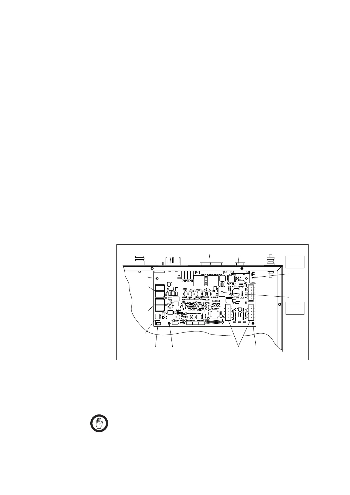
Figure 1.5 Modifying the SI board
g
h
b
c d
Torx T10
4.5lb·in
1)
1)
j
1!
1! ef
PZ1
4.5lb·in
Cables not shown.
i

 Loading...


