8 Multitone Paging Interface Fitting Instruction
© Tait Electronics Limited July 2008
4. Secure the panel in place using two M3 Nyloc nuts (352-00010-28
NUT M3 Nyloc hex), torque to 50cm.N (4.5in-lbs).
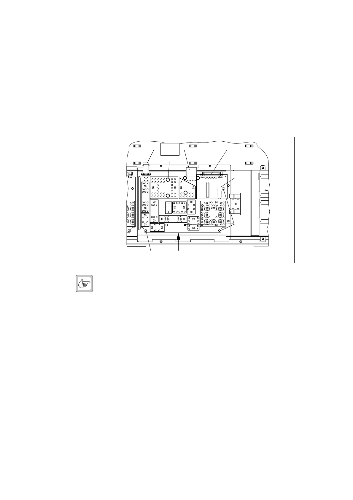
5. Use a Torx T10 screwdriver to remove the five screws
f and g
together with the spring washers and flat washers, put to one side.
6. Lift the receiver module clear of the chassis, put to one side.
7. Remove the metal heatsink
g for the audio PA, put to one side.
8. Put all the removed items into a plastic bag and retain as spares.
Note Although the boards of the transmitter and receiver modules look
alike, the transmitter board cannot be used in the receiver module
and the receiver board cannot be used in the transmitter module.
There is no heat transfer plate on the receiver module. Similar
boards from the Tait mobile radio range cannot be used as replace-
ments either.
1.5.4 Modifying the SI Board
Removal 1. Disconnect the system interface cables e to the transmitter and the
receiver, the fan control cable
f, the temperature sensor cable g, and
move them to one side.
2. Remove the DC power cables
h and i and put the cable connected
to
h to one side. Move the cable connected to i to one side.
Note the connection position for
i.
3. Remove the cable ties securing the cables that were connected to DC
power
c, system interface d, and the user interface e c onnector s.
Figure 1.4 Removing the receiver module
f
g
e
b
cd
f
Torx T10
4.5lb·in
Torx T10
4.5lb·in
h

 Loading...


