Multitone Paging Interface Fitting Instruction 7
© Tait Electronics Limited July 2008
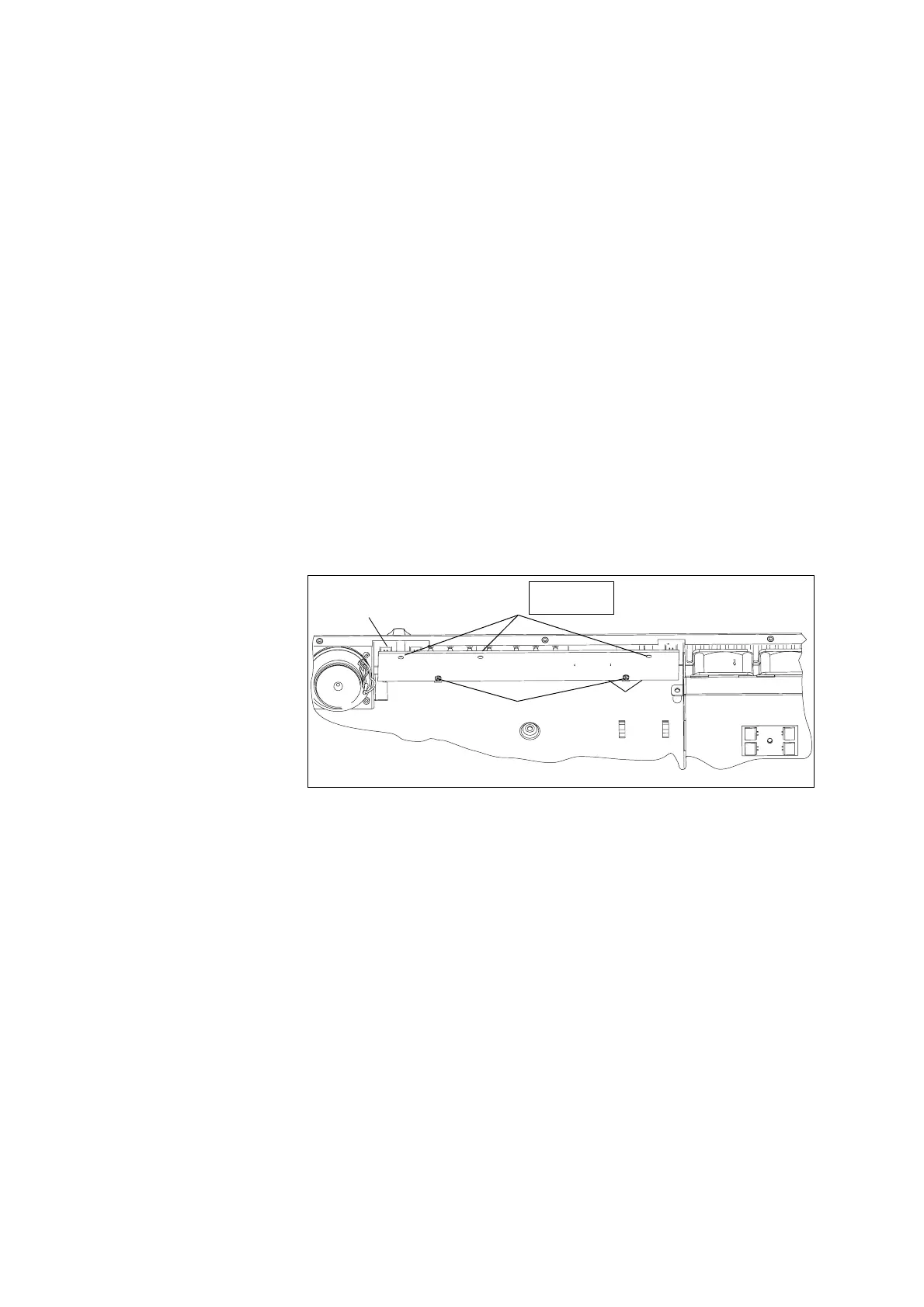
1.5.2 Removing the UI Board
1. Remove the volume knob by pulling slowly but firmly. The knob is
a friction fit and can leave the collet behind on the shaft. If this
happens, remove the collet from the shaft and place inside the knob.
2. Disconnect the speaker connector
b.
3. Use a Torx T10 screwdriver to remove the three screws
c together
with the spring washers and flat washers.
4. Insert the card remover tool (220-02034-xx) from the tool kit
(TBA0ST2), or a small flat-bladed screwdriver into the two small
holes at the bottom of the UI board. Lever the board completely off
the spring clips
d.
5. Carefully slide the UI board towards the rear of the Multitone paging
transmitter until the volume-control shaft clears the front panel. Lift
the UI board clear of the chassis.
6. Disconnect cable running from the receiver module to one of the two
Micro-MaTch connectors
e.
7. Keep the UI board disassembled until “Refitting UI board” on
page 14.
1.5.3 Removing the Receiver Module
1. Disconnect the cables to the RF b, DC power c, system interface
d, and the user interface e connectors.
2. Remove the Rx RF cable, connected to
b (219-02978-00 CBL
coax 400Ntype pnl skt BNC) from the rear panel. Place the cable
aside.
3. Fit the blanking panel (303-23055-00 CVR plt A4M955 N conn) to
th e i n s i de o f th e c h a s s i s co v eri n g t h e ne w R x h o l e i n t h e r e a r p a nel .
Figure 1.3 Removing the UI board
e
d
c
b
Cables not shown.
Torx T10
4.5lb·in (0.5N·m)

 Loading...


