6 Basic Tasks © Tait Electronics Limited February 2007
Setting Up the Equipment
For field calibration procedures, you need to remove the reciter from the
subrack to gain access to tuning holes. If a CTU is required for one procedure,
it is probably easiest to use it for all your procedures. If it is not required, you
can connect the PC directly to the reciter.
To set up the equipment
1. Remove the reciter from the subrack, following the instructions in the
Installation and Operation Manual. (Note that for some service center
procedures, the reciter can be left in the subrack.)
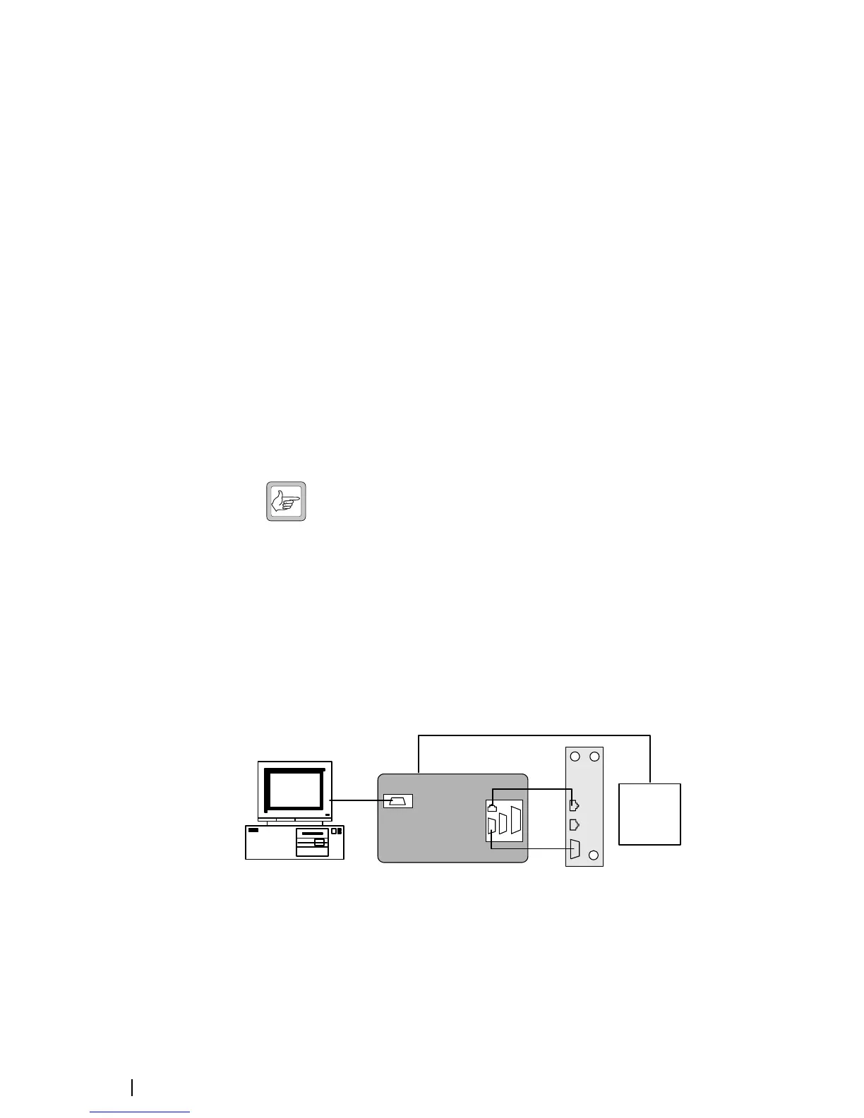
2. Connect the reciter and the PC to the CTU according to the diagram
below.
■ Connect the reciter’s analog RJ-45 socket (labeled AUD) to the CTU’s
RJ-45 using the RJ45 cable
■ Connect the reciter’s 9-way serial connector (labeled DIG) to the CTU’s
9-way male connector using the 9-way cable.
■ Connect your PC to the CTU by plugging an RS-232 cable into the 9-
way serial port labeled 10101.
(If you are not connecting via the CTU, connect the PC to DIG using the
RS-232 cable. No other connections are required.)
Note: Tait recommends that you disable the PC’s hardware
handshaking. The DIG connector is used for digital I/O as well as
for RS-232 and this could interfere with the handshaking.
Alternatively, use a special DB9 cable that has only three connectors (for pins
2, 3, and 5).
3. Connect the CTU to the 10-30V DC power supply using the power cable
supplied. If the base station’s PMU has a 12 V or 24 V auxiliary power
output, you can use this as the power supply. A connector is supplied with
the CTU. The reciter must also be supplied with power, but do not power
it up yet.
PC
BASE STATION
CALIBRATION TEST UNIT
RS-232
RJ45
CTU
Reciter
Power
supply
ETH
AUD
RS-232
Power cable
DIG
 Loading...


