TB9100 Calibration Software User’s Manual Adjusting the Frequency Setup 13
Adjusting the Exciter Lock Band
If you are preparing the base station for operation, adjusting the exciter lock
band is the third step in tuning the reciter. Alternatively, this procedure can be
performed independently of the other two calibration wizards on the
Frequency Setup tab. Adjusting the exciter lock band defines the range of
frequencies that the base station is able to transmit on.
Note: When performing this procedure, you don’t need to
terminate the exciter output port. An internal output pad means that
there is a good impedance match at this interface.
To calibrate the exciter lock band
1. Set up the equipment and connect the Calibration Software to the reciter.
2. Select the Frequency Setup tab, and double-click Set Exciter VCO. The
Set Exciter VCO Wizard appears.
3. Enter the center frequency (which must be a multiple of 500 kHz) of the
lock band that you want to use, and click Next.
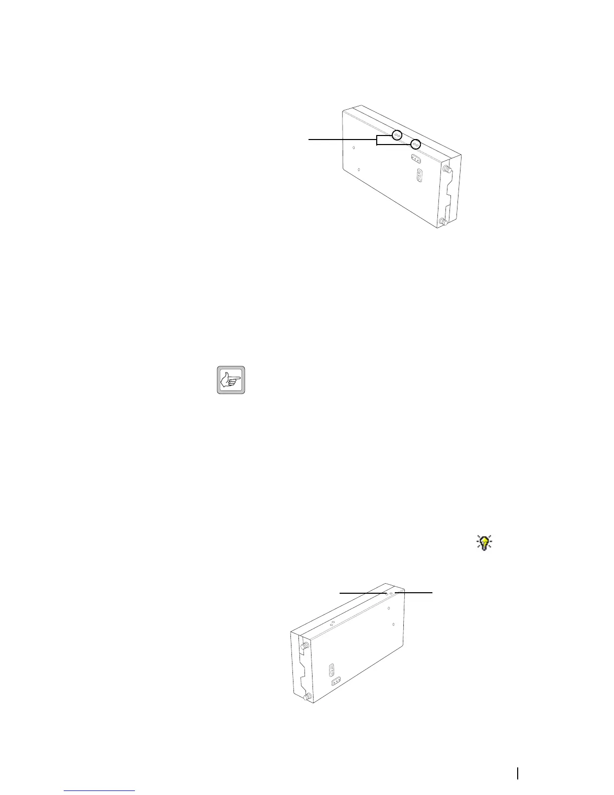
4. Insert the Murata tuning tool into the correct exciter VCO tuning hole (see
below) and adjust the trimmer until the actual band matches the desired
band. The bands turn green. Click Finish.
Once you have finished adjusting the exciter lock band, the icon on the
Frequency Setup tab indicates that this task is complete.
Trimmer holes for receiver
front-end tuning
(B band 136–174 MHz)
Exciter VCO tuning hole
for H band
(380–520 MHz)
Exciter VCO tunin
 Loading...


