Rollshutter Installation Instructions, 12
©Copyright TALIUS
diagrams for such systems are available upon request or can be found on mytalius.com. Under no circumstances should
the installer deviate from the wiring diagrams and change items or hook-up patterns. Never use any electrical
components that were not supplied by the manufacturer. Never connect wires of two or more tubular motors
together, unless specifically instructed on certain motor types. Tubular motors are highly specialized units with custom
designed switching mechanisms. Even simple looking items are specifically designed for these units. Any changes will
almost certainly result in catastrophic damage! Over the years we have seen motorized units damaged by
electricians who believed they comprehended the principles behind tubular motors. It is very tempting to see a simple
design in the motor configuration, but this is wrong. The description supplied with this job does not contain enough
information to explain the intricacies of a tubular motor and it cannot be deduced from the components! Finally, it is
essential that each Rollshutter dealer own a set of motor tester cables which can be obtained from the factory.
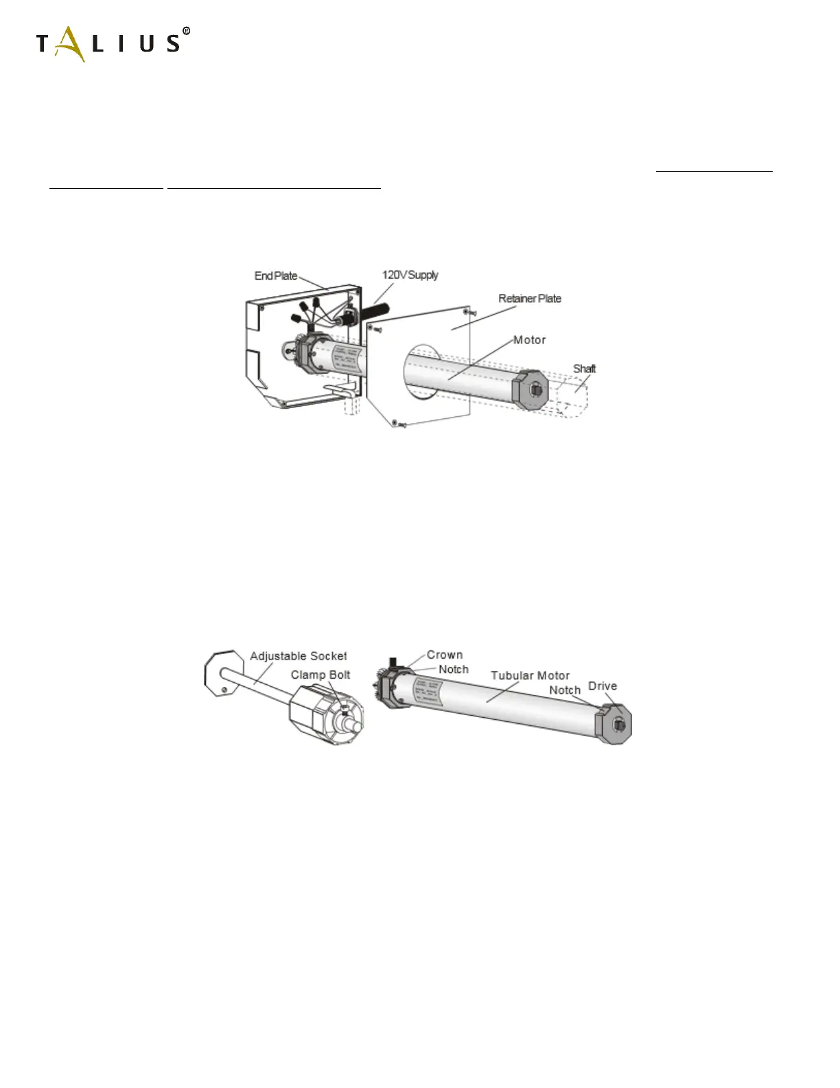
If the motor operator is equipped with a manual override begin by looking up Section 6.1a for the installation of the
manual override crank rod. If the motor is located in a panel box and fitted with a metal retainer plate, slide the retainer
plate away to clear access to the motor. Hook up the tester cables by matching the colour coded clamps to the
coloured wire ends. If a tester cable is not available have the electrician hook up the motor to the switching mechanism
as outlined in the wiring diagram. From this point on in the installation it is imperative that the motor is located fully
inside the shaft. Especially on rolling doors, ensure that the crown is securely located between the notch in the motor's
drum and the shaft. The shaft must be secured so that it cannot slide sideways, which requires that the clamp bolt on
the adjustable socket, if so outfitted, is screwed tight while pushing the socket against the end of the shaft. Switch the
tester cable so that the top of the shaft turns in the downward direction towards the panel box. Continue until the
motor comes to a stop by itself. The shaft has now reached what will later be its lower limit. The factory normally
presets the shaft so that it starts out already at or close to the lower limit. Therefore, the motor may not even have
operated at all or only for a very brief moment.