Rollshutter Installation Instructions, 11
©Copyright TALIUS
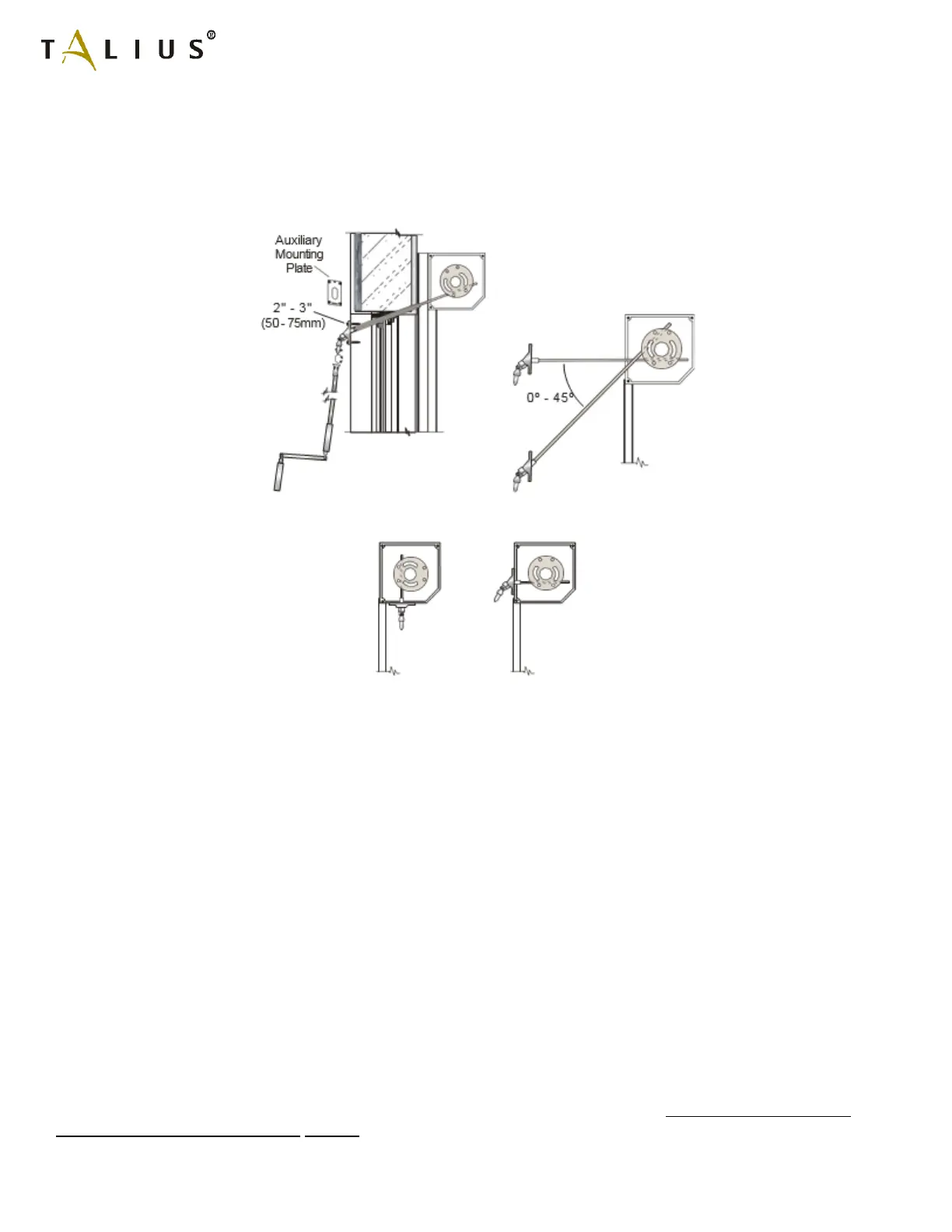
6.1b) Crank Rod Operator: If the operator runs through a wall, insert the universal with the connector through the hole in
the wall and ensure that the square connector inserts into the matching slots inside the gear. The connector will be too
long. Determine the excess length, remove the universal and cut it down to size with a hacksaw. Reinsert the cut-down
connector and attach the universal with two 2”-3” (50-75mm) long screws to the wall. In some cases, at the request of
the dealer, the factory will also supply an auxiliary mounting plate to be placed underneath the universal joint to provide
a stronger mounting plate.
If the operator does not run through a wall the universal joint will be attached directly to the panel box in a similar
manner. Most often the factory has already performed this.
Attach the crank rod. Crank rods are supplied in standard lengths of 68 ¼” and may be cut down to a comfortable size.
There are two styles of crank rod. The removable crank rod has a bell connector and can be slipped on and off the pin
of the universal at any time. The attached crank rod is slipped onto the pin of the universal and attached permanently
with the supplied expansion pin. Finally, attach the crank rod holder onto the wall with two 2" - 3" (50 - 75mm) long
screws. The holder keeps the rod in place when not being used. If the crank was attached to a motor with manual
override proceed to Section 7.
Once the crank is attached to a built-in gear, perform the following test to determine the type of gear in the panel box
and repeat the test for each Rollshutter in the job. Grab the shaft with both hands and attempt to turn it either way. If
the shaft can be moved in just one direction it is an A.B.S. gear (Anti-Block System) and you can proceed to the next
section. However, if the shaft cannot be moved at all, it is a gear with a built-in limit. Now turn the crank so that the top
of the shaft rotates in the down direction towards the back of the panel box. Continue until it reaches a limit in the gear
that prevents any further cranking. Normally the factory has pre-set the shaft rotations so that it is already at or very
near the built-in limit. This will later constitute the lower limit of the Rollshutter operation and will prevent anyone from
over-cranking the unit downwards.
6.1C) Spring-Loaded Operation: Proceed to Section 7.
6.1d) Motor Operator:
Important Notes: Most tubular Rollshutter motors operate on a volt- age of 120 Volts AC or more. In all States and
Provinces, regulations require that certified electricians perform all electrical hook-ups. The manufacturer strongly
recommends that all regulations be obeyed. Motorized units can be ordered with a variety of switching systems. Wiring