Description
of
the
PC
Modem
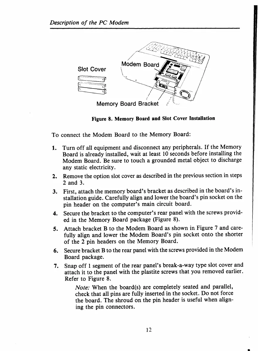
Slot
Cover
Memory
Figure
8.
Memory Board and
Slot
Cover Installation
To connect the Modem Board to the Memory Board:
1.
2.
3.
4.
5.
6.
1.
Turn off all equipment and disconnect any peripherals. If the Memory
Board is already installed, wait at least
10
seconds before installing the
Modem Board. Be sure to touch a grounded metal object to discharge
any static electricity.
Remove the option slot cover as described in the previous section in steps
2
and
3.
First, attach the memory board’s bracket as described in the board’s in-
stallation guide. Carefully align and lower the board’s pin socket on the
pin header on the computer’s main circuit board.
Secure the bracket
to
the computer’s rear panel with the screws provid-
ed in the Memory Board package (Figure 8).
Attach bracket B to the Modem Board
as
shown in Figure
7
and care-
fully align and lower the Modem Board’s pin socket onto the shorter
of
the
2
pin headers on the Memory Board.
Secure bracket B to the rear panel with the screws provided in the Modem
Board package.
Snap off
1
segment
of
the rear panel’s break-a-way type slot cover and
attach it to the panel with the plastite screws that you removed earlier.
Refer to Figure
8.
Note:
When the board@) are completely seated and parallel,
check that all pins are fully inserted in the socket.
Do
not force
the board. The shroud on the pin header is useful when align-
ing the pin connectors.
12
 Loading...


