Chapter
I
5.
6.
1.
With the rear panel of the computer facing you, remove the option slot
cover located on the top panel, place your thumb on the edge nearest
the front of the computer and press down to disengage the hook-latch
and slide the cover toward you.
Remove the option slot cover on the rear panel by removing the 6 plastite
screws.
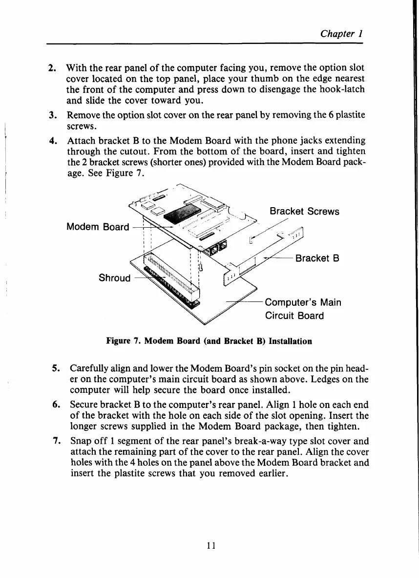
Attach bracket B to the Modem Board with the phone jacks extending
through the cutout. From the bottom of the board, insert and tighten
the
2
bracket screws (shorter ones) provided with the Modem Board pack-
age. See Figure
7.
Modem Board
Computer’s Main
Circuit Board
Figure
7.
Modem Board (and Bracket B) Installation
Carefully align and lower the Modem Board’s pin socket on the pin head-
er on the computer’s main circuit board as shown above. Ledges on the
computer will help secure the board once installed.
Secure bracket B to the computer’s rear panel. Align
1
hole on each end
of the bracket with the hole on each side of the slot opening. Insert the
longer screws supplied in the Modem Board package, then tighten.
Snap off
1
segment of the rear panel’s break-a-way type slot cover and
attach the remaining part of the cover to the rear panel. Align the cover
holes with the
4
holes on the panel above the Modem Board bracket and
insert the plastite screws that you removed earlier.
11
 Loading...


