Description
of
the
PC
Modem
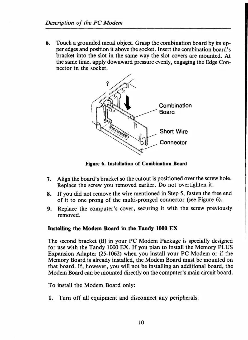
6.
Touch a grounded metal object. Grasp the combination board by its up-
per edges and position it above the socket. Insert the combination board’s
bracket into the slot in the same way the slot covers are mounted. At
the same time, apply downward pressure evenly, engaging the Edge Con-
nector in the socket.
Combination
Board
Short
Wire
Connector
Figure
6.
Installation
of
Combination Board
7.
Align the board’s bracket
so
the cutout is positioned over the screw hole.
Replace the screw you removed earlier.
Do
not overtighten it.
8.
If you did not remove the wire mentioned in Step
5,
fasten the free end
of it to one prong of the multi-pronged connector (see Figure
6).
9.
Replace the computer’s cover, securing it with the screw previously
removed.
Installing the Modem Board in the Tandy
1000
EX
The second bracket (B) in your PC Modem Package is specially designed
for use with the Tandy lo00
EX.
If you plan to install the Memory
PLUS
Expansion Adapter (25-1062) when you install your
PC
Modem or if the
Memory Board is already installed, the Modem Board must be mounted on
that board. If, however, you will not be installing an additional board, the
Modem Board can be mounted directly on the computer’s main circuit board.
To
install the Modem Board only:
1.
Turn off all equipment and disconnect any peripherals.
10
 Loading...


