DM-3200 Release Notes
16 TASCAM DM-3200 Release Notes V1.50
Assigning parameters to rotary encoders
You can assign parameters to the rotary encoders using the
four encoder mode keys (please refer to the “Encoders”
section on page 20 in the Owner’s Manual).
In the previous versions of DM-3200, parameters were
pre-assigned as indicated next to each of the encoder mode
keys. In Version 1.20 you can select which parameter is to
be controlled by which of the encoder mode keys.
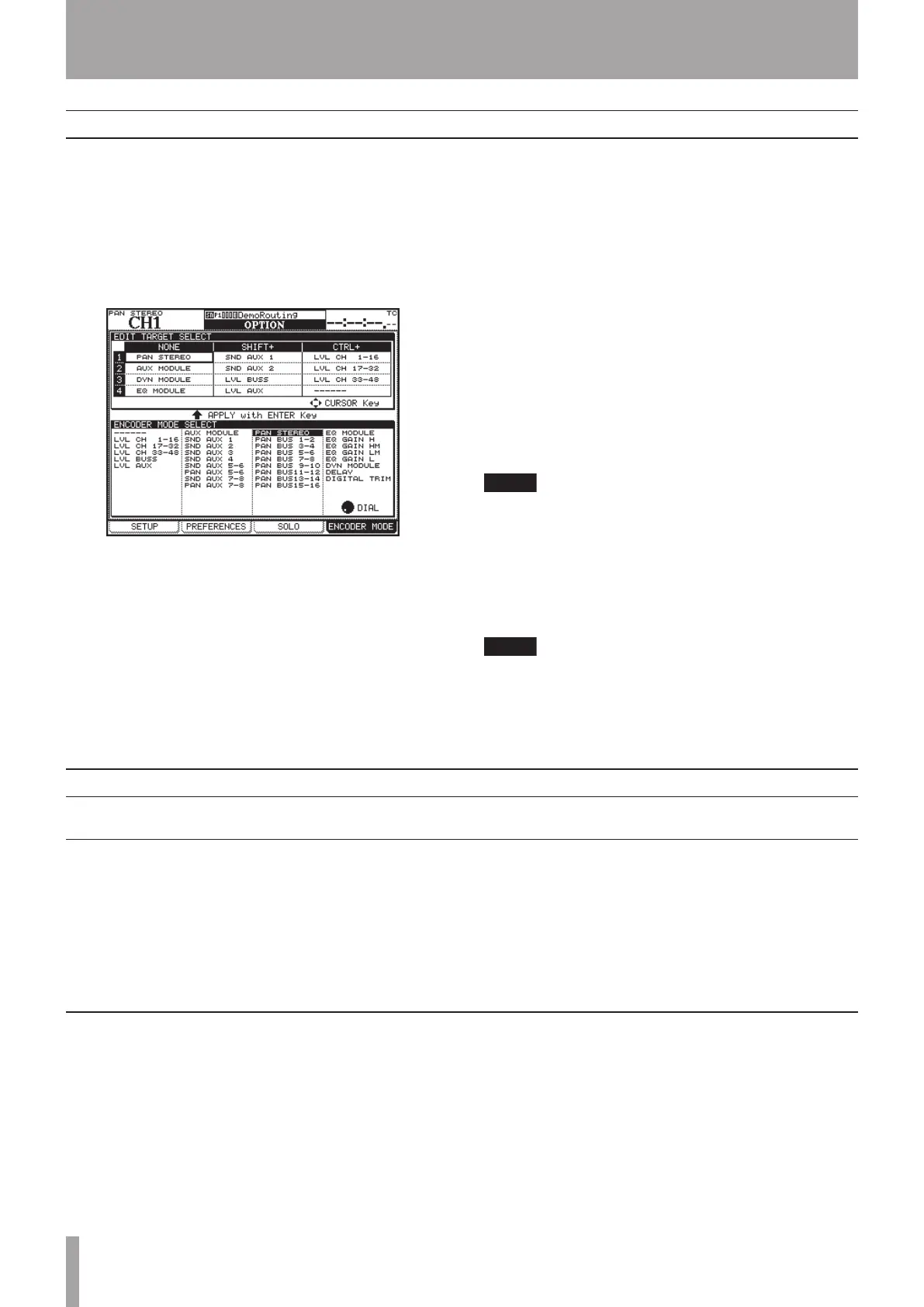
Figure 12: OPTION>ENCODER MODE scree
Parameters are assigned on the ENCODER MODE screen,
which is a sub-screen newly added to the OPTION screen.
1 Press the OPTION key to display the OPTION screen,
then use the POD 4 knob (or press the OPTION key
again) to display the ENCODER MODE sub-screen.
2 Use the CURSOR key to select the encoder mode
key to assign a parameter from the list in the EDIT
TARGET SELECT section.
Starting at the top, row numbers 1-4 represent the numbers
of the encoder mode keys.
“NONE” means that the encoder key is pressed by itself,
“SHIFT+” means that the encoder key and the SHIFT key
are pressed simultaneously, and “CTRL+” means that the
encoder key is pressed together with the CTRL key.
For example, if you want to assign a parameter to “the
topmost encoder mode key when it is pressed with the SHIFT
key,” select the field where row “1” and “SHIFT+” cross.
The encoder mode which is currently assigned to the
selected encoder mode key will be highlighted in the
ENCODER MODE SELECT section at the bottom of the screen.
3 Using the JOG/DATA dial, select the encoder mode
to be assigned to the highlighted encoder mode key,
from the ENCODER MODE SELECT section.
Depending on whether the surround mode is set to
STEREO or not, the options given in the ENCODER
MODE SELECT section differ.
4 Press the ENTER key.
Assignment of the parameter is now complete and
will be displayed in the EDIT TARGET SELECT section.
You need to perform the corresponding encoder
mode key operation in order to assign the set param-
eter to a rotary encoder.
Cascade connection
DM-3200 Ver1.20 allows you to make a cascade connection between two DM-3200 units.
Cascade connection overview
Two DM-3200 units that are connected by a cascade
connection can be operated as though they are one mixer.
STEREO buss, BUSS 1-16, AUX buss 1-8, and SOLO buss
can be shared when the sharing function is set to ON in
the CASCADE screen.
The audio clock is shared by the two units.
•
•
Timecode is shared to synchronize the two units.
Various settings and operations can be interlocked
between the two units. Please refer to the “Settings and
Operations that can be interlocked” section on page 9 of
this supplement.
•
•
You need to set one DM-3200 to be the cascade master and
the other to be the cascade slave. Any set-up that affects
the operation of the system as a whole will be performed
on the cascade master.
An audio clock source is selected from the clocks fed to
the cascade master. You cannot select the audio clock
source on the cascade slave.
Timecode fed to the cascade slave cannot be used as the
synchronization source.
•
•
The cascade connection can be turned ON and OFF only
on the cascade master.
When the cascade connection is ON, the parameter
set-ups on the cascade master (parameters to be inter-
locked) are reflected on the cascade slave.
•
•
Master/slave setting
 Loading...