18
Systems and Controls
Model 430
Mix Level Control (Thermistor Units)
The mix level control (P/N X41420) may be used in
both 115 volt and 208-240 volt applications. The
control has a switch (labeled SW4) that may be
changed to 240 volt or 115 volt by placing the switch
in the desired position. (See item “A” on page 19.)
Note: The factory default is 240 volts.
CAUTION: If 115 volts are connected to the control
and SW4 is in the 240 volt position, the control will not
respond to the mix out condition. If 208-240 volts are
connected to the control and the SW4 switch is in the
115 volts position, severe damage to the control will
take place.
The power hook-ups are located on the side of the
control. For proper connection, the terminals are
labeled “L1” and “L2”. (See item “B” on the mix level
control diagram on page 19.)
Probe terminals are labeled “COM”, “LOW”, and
“OUT”. (See item “C” on the mix level control diagram
on page 19.)
L1 output terminals are labeled “MIX LOW”, and “MIX
OUT”. Power supplied to the terminal labeled “L1” is
present at the “MIX OUT” terminal when no continuity
is established between the “COM” and “OUT”
terminals. Power supplied to the terminal labeled “L1”
is present at the “MIX LOW” terminal when no
continuity is established between the “COM” and
“LOW” terminals. When continuity of at least 2K ohms
resistance is established between the “COM” and
“OUT” terminals, L1 power will no longer be present at
the “MIX OUT” terminal.
When continuity of at least 2K ohms resistance is
established between the “COM” and “LOW” terminals,
L1 power will no longer be present at the “MIX LOW”
terminal. (See item D on the mix level control diagram
on page 19.)
There are two single pole double throw relays on the
control. This means there are two sets of three
terminals, and the center terminal of each set is the
common terminal. Only the “MIX OUT” relay is used in
the 430 application.
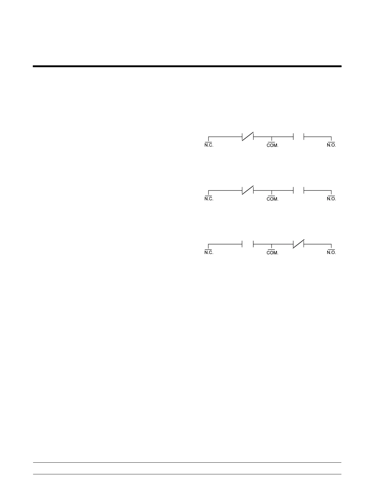
The following shows the position of the switch in the
three possible situations:
1. No power to the control.
2. Power to the control and no continuity
between the terminals.
3. Power to the control and continuity between
“COM” and “OUT” terminals.
On the mix level control board, there is a block of six
pins (item E on the control diagram). This block
(labeled J1) is used to allow the L1 power present at
the MIX OUT/LOW terminals to stay constant or pulse.
(When the power is constant the “MIX OUT/LOW”
LED’s will be lit; when the power pulses, the LED’s will
flash.)
At the Taylor factory, pins 3 & 5 and 4 & 6 on the J1
terminal are jumped together to create the pulse of
power. If pins 1 & 3 or 2 & 4 are jumped together, the
power would remain constant. Randomly jumping
other pins on the J1 terminal may cause damage.
Note: Terminals 1, 3, and 5 are used for the “MIX
OUT” feature. Terminals 2, 4, and 6 are used for the
“MIX LOW” feature.