Section 6
6-1
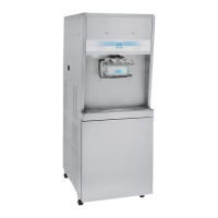
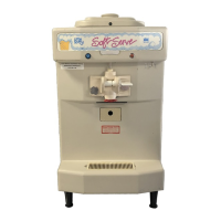
Model 8756
Operating Procedures
6
Operating Procedures
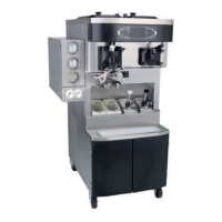
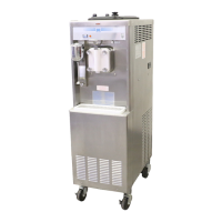
The Model 8756 has two freezing cylinders. The size of
each freezing cylinder is 3.4 qt (3.2 L). Mix is stored in
the lower front refrigerated compartment and is pumped
up to the freezing cylinder by an air/mix pump.
Duplicate the following procedures, where they apply, for
the second freezing cylinder.
We begin our instructions at the point where we enter the
store in the morning and find the parts laid out to air-dry
from the previous night's brush-cleaning.
If you are disassembling the machine for the first time, or
need information to get to this starting point in our
instructions, turn to
page 6-16, “Disassembly,” and start
there.
Assembly
WARNING! Make sure the power switch is in
the OFF position. Failure to follow this instruction may
result in severe personal injury from hazardous moving
parts.
Note: When lubricating parts, use an approved
food-grade lubricant (example: Taylor Lube).
Installing the Driveshaft
1. Lubricate the groove and shaft portion that comes in
contact with the bearing on the beater driveshaft.
Slide the seal over the shaft and groove until it snaps
into place. Do not lubricate the hex end of the
driveshaft.
2. Fill the inside portion of the seal with 1/4 in. (6.3 mm)
more lubricant and lubricate the flat side of the seal
that fits onto the rear shell bearing.
Figure 6-1
Note: For ease of cleaning, the seal may be turned
inside out. Make sure to position the seal correctly during
assembly.
Figure 6-2
11033
Apply the appropriate
Taylor approved food safe lubricant.