INSTRUCTION MANUAL
HWS 3000G
TDK-Lambda
<Page>
16/49
3-2. Connection method when using analog function
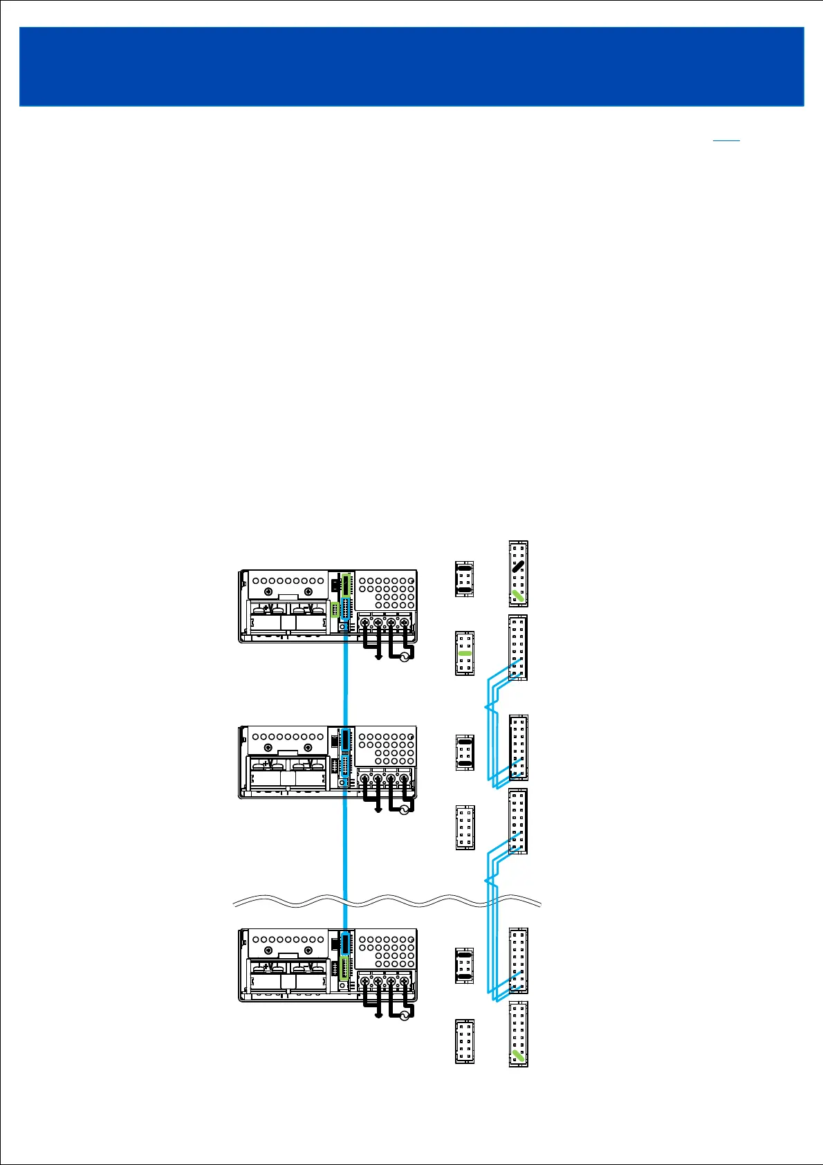
3-2-1. Leader-Follower function
Leader-Follower control allows multiple power supplies to be linked together with one control.
The controlling side is called the "leader machine" and the controlled side is called the "follower machine."
◆Pre-configuration
Before connecting multiple power supplies, set up the leader and follower devices.
<Leader machine setting>
Short-circuit between the L/E terminal (CN71 pin No. 6) and the DG terminal (CN71 pin No. 5 or pin No. 7).
<Follower machine setting>
Open the -R terminal (pin No.9 of CN41 and CN42).
◆Leader/follower connection
Connect the Leader machine to the starting point.
Connect between the +D terminals(CN41 or CN42 pin No.2), between the -D terminals(CN41 or CN42
pin No.1), and between the DG terminals(CN41 or CN42 pin No.4 or pin No.6) of all power supplies.
Short between the +D and -DR terminals(CN41 or CN42 pin No.3) of the leader machine and the last
follower machine.
The wires between +D terminals, -D terminals, and DG terminals should be the same length and as short as possible,
and twisted or shielded wires should be used.
TOPTOP