INSTRUCTION MANUAL
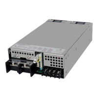
HWS 3000G
TDK-Lambda
<Page>
23/49
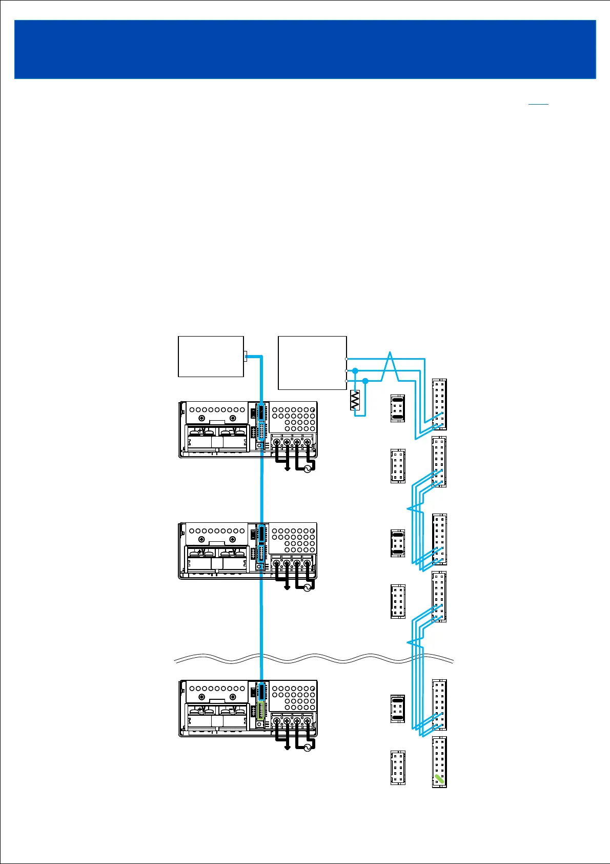
3-3. Connection method when using communication function
3-3-1. Connection method when using multiple power supplies in conjunction
Wiring starts from the power supply that connects to the host device.
Connect between the RS-485 + terminal of the host device and the +D terminal (CN41 or CN42 pin No. 2) of the power
supply to be connected. Connect between the RS-485 - terminal of the host device and the -D terminal (pin No. 1 of
CN41 or CN42) of the power supply to be connected. Connect between the RS-485 signal ground (SG) terminal of the
host device and the DG terminal (pin No. 4 or pin No. 6 of CN41 or CN42) of the power supply to be connected.
Starting from the power supply connected to the host device, connect "+D terminals, -D terminals, and DG terminals" of
all power supplies. Make a short connection between the +D terminal and -DR terminal (CN41 or CN42 pin No. 3) of the
last power supply. Connect the A/O terminal (pin No. 5 of CN42) of the starting power supply to the A/I terminal (pin
No. 5 of CN41) of the second power supply. Connect the A/O terminal (pin No. 5 of CN42) of the second power supply
to the A/I terminal (pin No. 5 of CN41) of the n-th power supply (last power supply).
Connect the terminating resistor to the RS-485 port of the host device. The host device may have a built-in termination
resistor. Please refer to the instruction manual of the host device.
Connect the CB and VB terminals as necessary.
Use twisted or shielded signal wires.
TOPTOP