INSTRUCTION MANUAL
HWS 3000G
TDK-Lambda
<Page>
24/49
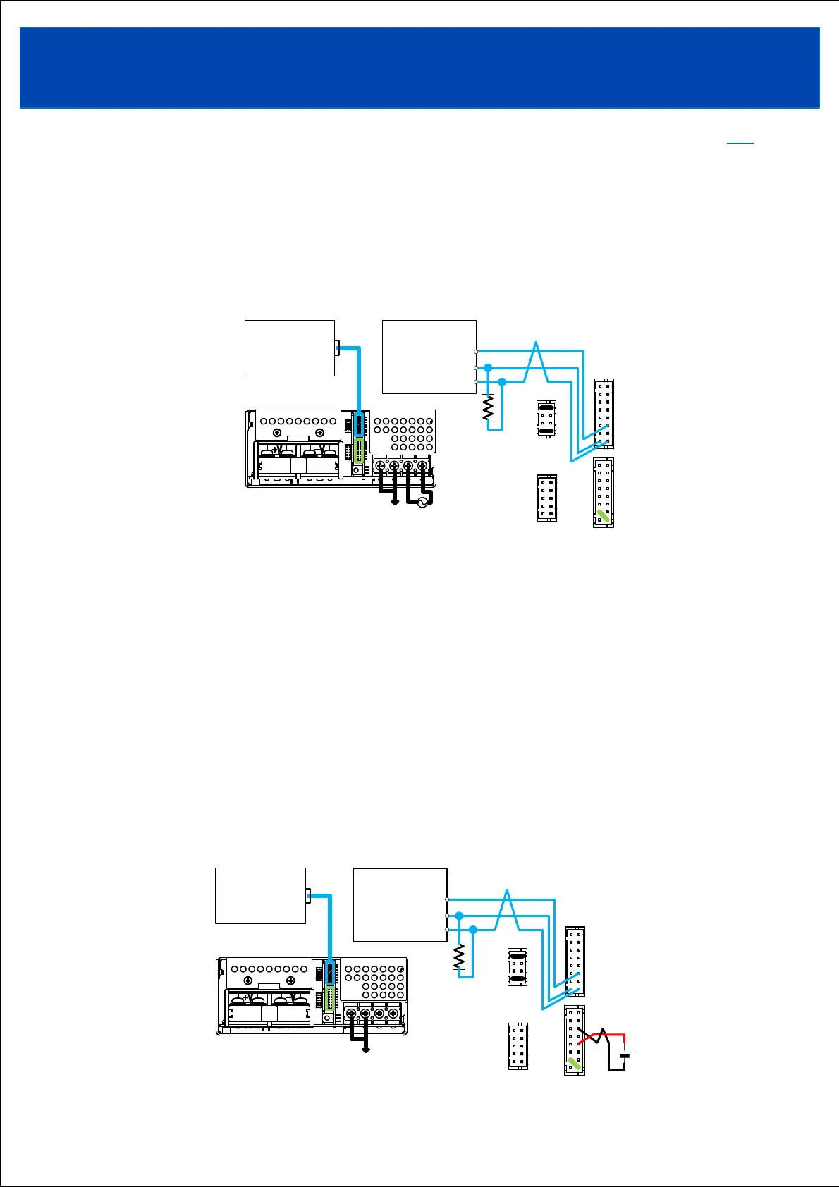
3-3-2. Case for use with one power supply
Connect between the RS-485 + terminal of the host device and the +D terminal (CN41 or CN42 pin No. 2) of the power
supply. Connect between the RS-485 - terminal of the host device and the -D terminal (CN41 or CN42 pin No. 1) of the
power supply. Connect the RS-485 signal ground Terminal (SG) of the host device and the DG terminal (pin No. 4 or
pin No. 6 of CN41 or CN42) of the power supply .
Connect between the +D terminal and -DR terminal (CN41 or CN42 pin No. 3) of the power supply.
Connect the terminating resistor to the RS-485 port of the host device. The host device may have a built-in termination
resistor. Please refer to the instruction manual of the host device.
Use twisted or shielded signal wires.
3-3-3. Cases for changing power output settings and checking operation history
Make the connections below. Setting changes and operation history can be checked without applying input
voltage to the power supply. Refer to the Communication Manual for details.
Connect an external voltage between the PWR terminal (pin No. 8 of CN41 or CN42) and the AG terminal
(pin No. 11 or pin No. 12 of CN41 or CN42).
Connect between the RS-485 + terminal of the host device and the +D terminal (pin No. 2 of CN41 or CN42) of the
power supply. Connect between the RS-485 - terminal of the host device and the -D terminal (CN41 or CN42 pin No. 1)
of the power supply. Connect the RS-485 signal ground terminal (SG) of the host device and the DG terminal (pin No. 4
or pin No. 6 of CN41 or CN42) of the power supply.
Connect between the +D terminal and -DR terminal (pin No. 3 of CN41 or CN42) of the power supply.
Connect the terminating resistor to the RS-485 port of the host device. The host device may have a built-in termination
resistor. Please refer to the instruction manual of the host device.
Use twisted or shielded signal wires.
・Be sure to disconnect the PWR terminal when using the product with input voltage applied.
If an external voltage is applied to the PWR terminal while input voltage is being applied, the protection function will
activate and cut off the output.
TOPTOP